Wednesday, December 31, 2008

TROUBLESHOOT DHCP

DHCP Stands for the Dynamic Host Configuration protocol and it is used to assign the IP addresses to the network computers dynamically. It saves the lot of time and the administrative efforts of the network administrators by providing the TCP/IP configurations such as IP address, subnet mask, default gateway address, DNS, router, proxy server and the settings to the client computers.

With the DHCP, the process of connecting the new client computer with the server is very easy. Just imagine that if you are assigned a task of provide the IP addresses and other TCP/IP configurations to1000 client computers manually then how lengthy and tiring task it can be. DHCP sever assigns the IP addresses from its predefined fixed pool of the IP addresses.

In the DHCP pool, you can define the range, leased duration and map the IP addresses with the specific computers. The IP addresses allocation can be manual, automatic and dynamic. Sometimes in the computer networks, DHCP failure occur due to several reasons and in this situation the client computer will not be able to connect to the server and get the server resources. The problems may arise at the client end or the DHCP server end.


DHCP Client Troubleshooting
Many Client Computers are unable to get the IP Addressees from the DHCP Server

It can be due to the reason that the IP address of the DHCP server has been changed and the client computers are not able to connect to the DHCP server. Additionally the client computers are located behind the firewall or are connected to the DHCP server through the router. It is also possible that the multiple DHCP servers exist in the same LAN.

The solutions of these problems are to make sure that the DHCP server’s IP address fall in the same range of the IP addresses as the scope it is serving. For a DHCP server to provide the IP address to the remote subnets, the router should act as DHCP relay. Make sure that you are not configuring the multiple DHCP servers on the same LAN with the same scope of the IP addresses as it can cause the conflicts in the IP addresses.

The DHCP client does not have IP addresses configured

It can happen due to the reason that the client computer is unable to connect to the DHCP server and obtain the IP address from it or the DHCP server is unavailable. To resolve this issue, you need to make sure that the client computer has connectivity with the DHCP server and the network cable and network connections are accurate. Then try to ping the DHCP server and make sure that you are getting reply from the server.

DHCP client has automatically assigned IP address to itself

In the Windows 98, XP Professional and the Windows ME sometimes the client computers are unable to connect to the DHCP server so they assign the IP addresses automatically through the IP auto configuration.

DHCP Server Troubleshooting

Sometimes if the multiple client computers are experiencing problems in leasing the IP address from the DHCP server then the problem is most likely with the DHCP server itself. The common problems that can arise in the DHCP server are the following.

DHCP server has been stopped

You need to check the log files and the system event files for details about this problem. These log files will provide the detailed information, causes and the solution of this problem.

One of Two DHCP Server is not serving the client

If this happens and if the server is a domain member then you need to authorize the DHCP server in the Active directory.

DHCP Server’s data is corrupted.

The DHCP server’s data has been corrupted or missing and possibly it generates the JET database errors. You need to use the DHCP data recovery options to recover the lost data and correct any of the generate errors. You can also use the reconcile feature in the DHCP console to verify and reconcile any inconsistencies in the database.

If you specific issue is not mentioned above then you need to visit the Microsoft’s website and review the DHCP troubleshooting articles for more details.

Testinside-ccna-640-802-v35

Exam Number/Code: 640-802
Exam Name: CCNA

"CCNA 's Cisco Certified Network Associate", also known as 640-802 exam, is a Cisco certification.
Preparing for the 640-802 exam? Searching 640-802 Test Questions, 640-802 Practice Exam, 640-802 Dumps?
With the complete collection of questions and answers, TestInside has assembled to take you through 200 questions to your 640-802 Exam preparation. In the 640-802 exam resources, you will cover every field and category in CCNA helping to ready you for your successful Cisco Certification.
http://www.youthgeneration.net/forum/index.php?topic=79.0

Sunday, December 14, 2008

Dell Wireless and Ubuntu Hardy Heron


I have a Dell Inspiron 1520 with the Dell Wireless 1390 WLAN Mini-Card, one that has given many Linux users big headaches.

After trying many different approaches suggested all over the web, and gathering clues in many Ubuntu forum posts, I finally worked out this solution:

First of all you must check if you have the correct card:

lspci -nn | grep 14e4

Result: 05:00.0 Network controller [0280]: Broadcom Corporation BCM94311MCG wlan mini-PCI [14e4:4311 (rev 01)]

Then proceed to the first step:

1. blacklist bcm43xx

echo blacklist bcm43xx | sudo tee -a /etc/modprobe.d/blacklist

2. install ndiswrapper and related files

sudo apt-get install ndiswrapper-common ndiswrapper-utils-1.9 ndisgtk

3. download http://ftp.us.dell.com/network/R174291.exe

this is a ridiculous bit of bloat, but the most complete INF for 43xx devices

4. Unzip the drivers.

5. go into folder DRIVER_US inside the result of what you did above

6. use ndiswrapper to install bcmwl5.inf

System -> Administration -> Windows Wireless Drivers -> Install New Driver -> Select bcmwl5.inf from ~/R151517/DRIVER_US

7. Modify rc.local

gksudo gedit /etc/rc.local

Insert these lines ABOVE “exit 0″ line:

modprobe -r b44
modprobe -r ssb
modprobe -r ndiswrapper
modprobe ndiswrapper
modprobe ssb
modprobe b44

8. Restart or simply paste one by one the following lines:

$ sudo rmmod b44
$ sudo rmmod ssb
$ sudo rmmod ndiswrapper
$ sudo modprobe ndiswrapper
$ sudo modprobe ssb
$ sudo modprobe b44

You should see the WiFi led on and you are good to go.

Easy switching network settings (home & office)

You can easily switch your network settings using the netsh command, instead of installing a lot of unnecessary software. Here are two examples, one for dhcp settings, and one for a static address. You can put it into a .bat file:

netsh interface ip set address "Net" source=dhcp
netsh interface ip set address "Net" static 192.168.0.xx 255.255.255.0 192.168.0.1 1

192.168.0.xx is your ip address, followed by the netmask and gateway. The last 1 is the metric. Optionally you can adjust your DNS values as well using set DNS instead of set address. This command helped me switching easily between my home network settings using dhcp and my office where there is a static address.

SSH login without password

If you want to make a bakup script like the one I showed you yesterday, you may need to set your machines to login remotely without asking for a password everytime. This is done by sharing between them the public rsa keys generated by the openssh server.

Login as the user you will use for the transfer script and run:

ssh-keygen -t rsa

Answer the questions but do not enter a password because otherwise you will still need to to pass it when the script runs. You should then have two new files in ~/.ssh, id_rsa and id_rsa.pub. Open id_rsa.pub with your favorite editor and copy everything (there is only one line actually) into the ~/.ssh/authorized_keys on the second machine (the one in which you need to copy).

Now try to login and if everything was set properly it won’t ask you for a a password anymore.

Simple script to backup virtual machines in linux

Currently I am using a small VMWare Server hosting 4 virtual machines, and i found my self in the position of backing them up. But the virtual machines need to be stopped before you can copy them somewhere else. Using the getstate() output of the vmware-cmd you can find the state of each virtual machine. using the following script you can set a cron job to backup your vitual machine:


#!/bin/sh
PATH="/srv/vmware-server/Contabilitate/Windows XP Professional.vmx"
CMD=$(vmware-cmd "$PATH" getstate)

case $CMD in
"getstate() = on")
vmware-cmd "$PATH" suspend
rsync -avz --stats --progress -e ssh /srv/vmware-server/Contabilitate root@192.168.0.3:/mnt/bak/04
rsync -avz --stats --progress -e ssh /srv/vmware-server/Contabilitate root@192.168.0.9:/var/bak/04
vmware-cmd "$PATH" start
;;
*)
esac

Export CSV from MySql Database via SSH

There is a time when you need to export a specific table from a mysql database. Through SSH this is made very easy using the following command:

echo “select * from table_name;” | mysql -u root -pyourpassword database_name | sed -e ’s/^Mn/r/g’ > /home/exported.csv

Of course you can make a small script that adds the date or other usefull information to the filename:

#!/bin/bash
#This scripts adds date to the exported CSV
NOW=$(date +”%m_%d_%Y_%H_%M_%S”)
echo “select * from table_name;” | mysql -u root -pyourpassword database_name | sed -e ’s/^Mn/r/g’ > /home/exported_$NOW.csv

Save this script as export_csv.sh and make it executable, and that’s it.

Wednesday, December 3, 2008

VPN for Linux Installation

VPN for Linux
Installation

These steps have been tested on recent versions of RedHat, Fedora, Ubuntu, and Slackware.

1. Obtain the IPSec Group Name and IPSec Password for either on campus use or off campus use by clicking the following link: VPN Account Information.
2. If prompted, enter your SacLink User ID and Password. If you have not created your account or have forgotten your account ID or password, see SacLink Information for details.
3. Obtain the VPN client from the Software Distribution Web Site by clicking the following link: http://software.csus.edu/
4. Click on the Obtain Software link in the left navigation bar.
5. Read and agree to the terms of distribution by clicking the I Agree link at the bottom of the page.
6. Log in using your SacLink username and password.
7. Locate the Cisco VPN Client for your operating system and click the Download link.
8. Click the Download Now button.
9. Save the file to your home directory. The file could take a few minutes to download depending on your connection speed.
10. Once the file is downloaded, close your browser.
11. Open a terminal session. How this is done depends on your distribution of Linux and whether or not you are running X windows.
12. Change directory to where you downloaded the file. If you downloaded the file to your home directory, simply type cd
13. Unpack the file that you have downloaded by typing
tar xvzf vpnclient-linux-4.0.1.A-k9.tar.gz
14. Change directory to the newly unpacked directory
cd vpnclient
15. You need to be the root user (superuser) to run the install script.
Type su and press enter.
16. Enter the root password.
17. To install the client type: ./vpn_install
18. Accept all the default selections by pressing the Enter key.
19. Restart your computer, or type (as root)
/etc/rc.d/init.d/vpnclient_init start
to start the vpn client without restarting.

Configuration

The following instructions assume you are using the vi (vee-eye) text editor. But you can use any text editor, such as emacs or pico (the instructions will vary slightly depending on your choice of editor).

1. Open a terminal session and become root (superuser).
2. Type su and press enter. Enter the root password.
3. Create a User Profile for the VPN Client. The default location of the sample profile is /etc/CiscoSystemsVPNClient/Profiles/.
4. Type cd /etc/CiscoSystemsVPNClient/Profiles/
5. Type ls
6. You must copy the sample.pcf file and rename it. To do so, type
cp sample.pcf oncampus.pcf
(offcampus.pcf for off campus connections).
7. Typevi oncampus.pcf
8. Using the arrow keys on the keyboard, place the cursor after the = sign at the Description prompt.
9. Press the esc key and then the x key, to delete the previous information.
10. Press the esc key and then the i key, to enter the new information.
11. Type Sac State On Campus VPN Connection or Sac State Off Campus VPN Connection at the prompt for the Description.
12. Using the arrow keys on the keyboard, place the cursor after the = sign at the Host prompt.
13. Press the esc key and then the x key, to delete the previous information.
14. Press the esc key and then the i key, to enter the new information.
15. Type vpn.csus.edu at the prompt for Host.
16. Using the arrow keys on the keyboard, place the cursor after the = sign at the GroupName prompt.
17. Press the esc key and then the x key, to delete the previous information.
18. Press the esc key and then the i key, to enter the new information.
19. Type the IPSec Group name you obtained from the VPN Account Information document.
20. Using the arrow keys on the keyboard, place the cursor after the = sign at the Username prompt.
21. Press the esc key and then the x key, to delete the previous information.
22. Press the esc key and then the i key, to enter the new information.
23. Type your SacLink login name at the Username prompt. The file should look like the On Campus or Off Campus sample.
24. Save the new profile by pressing the esc key followed by a colon and letters wq and then press enter (esc :wq enter).

Running the Client

1. Connect to the Internet.
2. Open a terminal session.
3. Type the following:
vpnclient connect profile
(where profile for on campus connections is: oncampus; and for off campus connections is: offcampus ).
4. It will prompt you to enter the group password.
5. It will display your SacLink user name.
6. At the password prompt, type your SacLink password.
7. The VPN services should now be enabled.
8. Connect to the Internet.

Saturday, November 29, 2008

CCNA: List of Simulator Tool

Followings are CCNA simulator tool for practicing CCNA

Packet Tracer - Packet Tracer 5.0 is the latest version of Cisco Networking Academy’s comprehensive networking technology teaching and learning software. Innovative features of Packet Tracer 5.0, including powerful simulation, visualization, authoring, assessment, and collaboration capabilities, will help students and teachers collaborate, solve problems, and learn concepts in an engaging and dynamic social environment. Moreover, it's totally free! You can download this software but you need to register first or you can find a mirror download with google (with keyword "download packet tracer")

Screen shots:


SemSim - The free trial version (2.3MB) offers some CCNA exam router simulation labs & 20 flash cards

Screen shots:


Boson NetSim - Boson offers three certification-focused products, NetSim for CCENT 7.0, NetSim for CCNA 7.0 and NetSim for CCNP 7.0. The NetSim for CCNA 7.0 product contains CCNA-specific lab exercises that cover the skill set you will need to prepare for your CCNA exam. The demo version (21.58MB) is a good choice to get started.

Screen shots:


CertExams offers advanced network simulators including router / switch / terminal simulator. The simulators help in preparing for networking exams such as ccna or jncia. It would also be very helpful for those who want to get started with configuring Cisco or Juniper routers in a simulated environment. The demo version (6.95MB) is limited to:

- Six lab exercises

- Router simulator is limited to User EXEC, Previleged EXEC, and Global Configuration mode commands.

Screenshots:


RouterSim's CCNA Network Visualizer - You can design, build and configure your own network. The demo version is 44.49MB. It is ideal for:

- Anyone studying for the Cisco® CCNA™ 640-802 exam

- Deployment over a LAN network

- Distance education and deployment on a Citrix server or Microsoft Terminal Services

- Corporate trainers and employees

- Students at colleges, universities, and technical institutes

Screen shots:


Thursday, November 27, 2008

How to Connect to a Network Printer in Windows XP

For most home users it is very easy to connect to a printer. Older printers are usually connected to the parallel port, while the new printers are connected to the USB port. Once the printer is connected and drivers loaded you can easily select the printer from the list and begin printing.

For those on a network that have printers you can use, you have to take different steps to connect to the printers. While the steps to connect to a network printer are different than connecting to a local print, they aren’t complex and can be performed very easily.

Network Printers

Unlike local printers, network printers are usually connected to a server somewhere on the network. Connecting printers in this manner allows many people to use the printers very easily without having to disconnect and reconnect the printer.

Any printer can be connected to the network, even printers used at home. Describing how to do that is beyond the scope of this post, but I’ll look into writing one in the future. To connect to a network printer you would need the name of the server connected to the printer, and the name of the printer. Once you have those two pieces of information you can connect to the printer.

Connecting to a Network Printer

To connect to a network printer, simply do the following:

  1. Click Start->Settings->Printers and Faxes. This will display a window listing all printers currently setup on your computer.
  2. Click the Add a printer icon to start the Add Printer Wizard.
  3. On the first screen, click the Next button.
  4. On the Local or Network Printer screen, select the A network printer, or a printer attached to another computer) option, and then click Next.
  5. Since you know the server and printer name (hopefully), select the Connect to this printer (or to browser for a printer, select his option and click Next option.
  6. Enter the server and printer name in the format: \\[server name]\[printer name]. For example, if your server name is printserv and your printer name is laserprinter, then the path would be \\printserv\laserprinter.
  7. Once you enter the name, click Next to continue.
  8. When a connection to the printer is established, and you have other printers currently installed, you will be prompted to set the new printer as the default printer. This means that when you click the print button in an application, this printer will be the one automatically selected first.
  9. Select Yes to make the new printer the default, or No to keep the current default printer. When done, click Next to continue.
  10. A summary of the newly added printer appears. When you are finished reading the information, click Finish to continue.

You have successfully installed a new network printer to your computer.

CCNA Lab Manual - A good book for beginner


Link download:
CCNA Lab Manual

Router Boot-up Process

Router Boot-up Process

There are four major phases to the bootup process:
1. Performing the POST
2. Loading the bootstrap program
3. Locating and loading the Cisco IOS software
4. Locating and loading the startup configuration file or entering setup mode

1. Performing the POST
The Power-On Self Test (POST) is a common process that occurs on almost every computer during bootup. The POST process is used to test the router hardware. When the router is powered on, software on the ROM chip conducts the POST. During this self-test, the router executes diagnostics from ROM on several hardware components including the CPU, RAM, and NVRAM. After the POST has been completed, the router executes the bootstrap program.

2. Loading the Bootstrap Program
After the POST, the bootstrap program is copied from ROM into RAM. Once in RAM, the CPU executes the instructions in the bootstrap program. The main task of the bootstrap program is to locate the Cisco IOS and load it into RAM.
Note: At this point, if you have a console connection to the router, you will begin to see output on the screen.

3. Locating and Loading Cisco IOS
Locating the Cisco IOS software. The IOS is typically stored in flash memory, but can also be stored in other places such as a TFTP (Trivial File Transfer Protocol) server.
If a full IOS image can not be located, a scaled-down version of the IOS is copied from ROM into RAM. This version of IOS is used to help diagnose any problems and can be used to load a complete version of the IOS into RAM.
Note: A TFTP server is usually used as a backup server for IOS but it can also be used as a central point for storing and loading the IOS. IOS management and using the TFTP server is discussed in a later course.

4. Locating and Loading the Configuration File
Locating the Startup Configuration File. After the IOS is loaded, the bootstrap program searches for the startup configuration file, known as startup-config, in NVRAM. This file has the previously saved configuration commands and parameters including:
interface addresses
routing information
passwords
any other configurations saved by the network administrator
If the startup configuration file, startup-config, is located in NVRAM, it is copied into RAM as the running configuration file, running-config.
Executing the Configuration File. If a startup configuration file is found in NVRAM, the IOS loads it into RAM as the running-config and executes the commands in the file, one line at a time. The running-config file contains interface addresses, starts routing processes, configures router passwords and defines other characteristics of the router.

Enter Setup Mode (Optional). If the startup configuration file can not be located, the router prompts the user to enter setup mode. Setup mode is a series of questions prompting the user for basic configuration information. Setup mode is not intended to be used to enter complex router configurations, and it is not commonly used by network administrators.
When booting a router that does not contain a startup configuration file, you will see the following question after the IOS has been loaded:

Command Line Interface
Depending on the platform and IOS, the router may ask the following question before displaying the prompt:
Would you like to terminate autoinstall? [yes]:
Press the Enter key to accept the default answer.
Router>
Note: If a startup configuration file was found, the running-config may contain a hostname and the prompt will display the hostname of the router.
Once the prompt displays, the router is now running the IOS with the current running configuration file. The network administrator can now begin using IOS commands on this router.
Note: The bootup process is discussed in more detail in a later course.

Tuesday, November 18, 2008

CCNA Exam Topic : Planning & Designing

CCNA Exam Topic : Planning & Designing

CCNA Planning & Designing topic explains all the actual and real questions that would be on ccna test.

Question 1:
Which of the following host addresses are members of networks that can be routed across the public Internet?(Choose three.)
A. 10.172.13.65
B. 172.16.223.125
C. 172.64.12.29
D. 192.168.23.252
E. 198.234.12.95
F. 212.193.48.254

Answer: CEF

Explanation:
Private IP address scheme
Class A: 10.0.0.0 – 10.255.255.255
Class B: 172.16.0.0 – 172.31.255.255
Class C: 192.168.0.0 – 192.168.255.255
Other then private ip addresses remaining IP’s addresses are routed across internet.

Question 2:
Given a subnet mask of 255.255.255.224, which of the following addresses can be assigned to network hosts?
(Choose three.)
A. 15.234.118.63
B. 92.11.178.93
C. 134.178.18.56
D. 192.168.16.87
E. 201.45.116.159
F. 217.63.12.192

Answer: BCD

Explanation:
For calculating network hosts range for subnet 255.255.255.224
Simple method to find out network subnet is 256 -224 = 32
Write down the multiples of 32 to get subnet networks
Host range for subnet 255.255.255.224 are between this ranges below
0 ----- 31 (0 is network address and 31 is broadcast address)
32 -----63
64 -----95
96 -----127
128 ----159
160---- 191
192 ----223
224 ----255

Question 3:
When variable length subnet masking is used, what does the term route aggregation describe?
A. calculating the total number of available host addresses in the AS
B. combining routes to multiple networks into one supernet
C. reducing the number of unusable addresses by creating many subnets from one supernet
D. reclaiming unused address space by changing the subnet size

Answer: B

Explanation:
Route aggregration is an effort to route smaller prefixes via an aggregated larger prefix (supernetting). The advantage is obvious: Many /24 networks, for example, could be aggregated to larger networks like /23, /22 or even bigger prefixes.

Question 4:
ABC Company is merging with several local businesses that use routers from multiple vendors. Which routing protocol would work best to connect ABC Company with the enterprise networks it has acquired by providing scalability and VLSM support while minimizing network overhead?

A. RIP v1
B. RIP v2
C. IGRP
D. OSPF
E. EIGRP

Answer: D

Explanation:
Since only OSPF,EIGRP and RIPv2 supports VLSM in above options. It requires working with multi vendor and providing scalability OSPF is best choice of the three mentioned.

Question 5:
Which of the following IP addresses fall into the CIDR block of 115.64.4.0/22? (Choose three.)
A. 115.64.8.32
B. 115.64.7.64
C. 115.64.6.255
D. 115.64.3.255
E. 115.64.5.128
F. 115.64.12.128

Answer: BCE

Explanation:
/22 is 8bits + 8bits + 6bits i.e 11111111.11111111.11111100.0
Third octet 11111100 = 128+64+32+16+8+4
= 252 therefore subnet mask is 255.255.252.0
Subnet networks are 256-252= 4
Host range for above subnet are
0------- 3
4 ------ 7

Host that fall under 115.64.4.0 /22 networks are
4 5 6 7

Question 6:
In the implementation of VLSM techniques on a network using a single Class C IP address, which subnet mask is the most efficient for point-to-point serial links?
A. 255.255.255.0
B. 255.255.255.240
C. 255.255.255.248
D. 255.255.255.252
E. 255.255.255.254

Answer: D

Explanation:
For point-to-point serial link exist only two hosts so the best possible subnet mask for two useable hosts for class C network is 255.255.255.252

Question 7:
Which statements are true regarding classless routing protocols? (Choose two.)
A. The use of discontiguous subnets is not allowed.
B. The use of variable length subnet masks is permitted.
C. RIP v1 is a classless routing protocol.
D. IGRP supports classless routing within the same autonomous system.
E. RIP v2 supports classless routing.

Answer: BE

Question 8:

The company internetwork is subnetted using 29 bits. Which wildcard mask should be used to configure an extended access list to permit or deny access to an entire subnetwork?
A. 255.255.255.224
B. 255.255.255.248
C. 0.0.0.224
D. 0.0.0.8
E. 0.0.0.7
F. 0.0.0.3

Answer: E

Explanation:
29 bits subnet is 8bits + 8bits + 8bits + 5bits
255.255.255.(5bits)
11111000 = 128+64+32+16+8+0+0+0
= 248
Subnet is 255.255.255.248
Simple method to calculate the Wildcard mask from known subnet is to
Reverse 1’s into 0’s and 0’s into 1’s from the binary representation of subnet.
For above example (248 = 11111000 subnet)
11111000 (subnet) = 00000111 (wildcard mask) last octet.
= 7 (wildcard mask) for last octet.
Converting the remaining first 3 octets of subnet into wildcard mask using above method
Resulted wildcard mask is 0.0.0.7

Question 9:
The MDA Company is implementing dialup services to enable remote office employees to connect to the local network. The company uses several different Layer 3 protocols on the network. Authentication of the users connecting to the network is required for security. Additionally, some employees will be dialing long distance and will need callback support. Which protocol is the best choice for these remote access services?
A. 802.1
B. Frame relay
C. HDLC
D. PPP
E. SLIP
F. PAP

Answer: D

Question 10:
Refer to the diagram. All hosts have connectivity with one another. Which statements describe the addressing scheme that is in use in the network? (Choose three.)

A. The subnet mask in use is 255.255.255.192.
B. The subnet mask in use is 255.255.255.128.
C. The IP address 172.16.1.25 can be assigned to hosts in VLAN1
D. The IP address 172.16.1.205 can be assigned to hosts in VLAN1
E. The LAN interface of the router is configured with one IP address.
F. The LAN interface of the router is configured with multiple IP addresses.

Answer: BCF

Question 11:
Which routing protocols will support the following IP addressing scheme? (Choose three.)
A. RIP version 1
B. RIP version 2
C. IGRP
D. EIGRP
E. OSPF

Answer: BDE

Question 12:
A company with 25 computers decides to connect its network to the Internet. The company would like for all of the computers to have access to the Internet at the same time, but the company only has four usable public IP addresses. What should be configured on the router so that all computers can connect to the Internet simultaneously?
A. static NAT
B. global NAT
C. dynamic NAT
D. static NAT with ACL’s
E. dynamic NAT with overload

Answer: E

Question 13:
A network administrator would like to implement NAT in the network shown in the graphic to allow inside hosts to use a private addressing scheme. Where should NAT be configured?

A. Corporate router
B. Engineering router
C. Sales router
D. all routers
E. all routers and switches

Answer: A

Question 14:
Which of the following describe private IP addresses? (Choose two.)
A. addresses chosen by a company to communicate with the Internet
B. addresses that cannot be routed through the public Internet
C. addresses that can be routed through the public Internet
D. a scheme to conserve public addresses
E. addresses licensed to enterprises or ISPs by an Internet registry organization

Answer: BD

Question 15:
Refer to the graphic. A host is connected to switch port Fa0/3 with a crossover cable. The host and switch have been fully configured for IP connectivity as shown. However, the port indicator on switch port Fa0/3 is not on, and the host can not communicate with any other hosts including those connected to VLAN 2 on the same switch. Based on the information given, what is the problem?
A. Switch port Fa0/3 is not configured as a trunk port.
B. The cable is the wrong type.
C. The switch has been assigned an incorrect subnet mask.
D. Switch port Fa0/3 has been blocked by STP.
E. The switch and the hosts must be in the same subnet.

Answer: B


Explanation:
Straight through cable is used to connect a host to switch.

Question 16:
What kind of cable should be used to establish a trunked link between two Catalyst 2950 switches?
A. a straight-through cable
B. an EIA/TIA-232 serial cable
C. an auxiliary cable
D. a modem cable
E. a cross-over cable

Answer: E

Explanation:
Cross-over cable is used to connect two switches.

Question 17:
What is the purpose of Spanning Tree Protocol?
A. to prevent routing loops
B. to create a default route
C. to provide multiple gateways for hosts
D. to maintain a loop-free Layer 2 network topology
E. to enhance the functions of SNMP

Answer: D


Question 18:
The network 172.25.0.0 has been divided into eight equal subnets. Which of the following IP addresses can be assigned to hosts in the third subnet if the ip subnet-zero command is configured on the router? (Choose three.)
A. 172.25.78.243
B. 172.25.98.16
C. 172.25.72.0
D. 172.25.94.255
E. 172.25.96.17
F. 172.25.100.16

Answer: ACD


Question 19:
Which wild card mask will enable a network administrator to permit access to the Internet for only hosts that are assigned an address in the range of 192.168.8.0 through 192.168.15.255?
A. 0.0.0.0
B. 0.0.0.255
C. 0.0.255.255
D. 0.0.7.255
E. 0.0.3.255

Answer: D

Question 20:
The exhibit shows a company network. The network administrator would like to permit only hosts on the 172.30.16.0/24 network to access the Internet. Which wild card mask and address combination will only match addresses on this network? A. 172.30.0.0 0.0.0.0
B. 172.30.16.0 0.0.0.255
C. 172.30.0.0 0.0.15.255
D. 172.30.16.0 0.0.31.255
E. 172.30.16.0 0.0.255.255

Hotspot 2: Topology Question

Hotspot 2: Topology Question

640-802 CCNA Hotspot Topology Exhibit


Question 1:
Note: host 172.30.4.4 is wrongly given in Question the correct host must be 172.30.0.4


Answers: 702

Explanation:
The destination layer 2 address is a DLCI for frame-relay network. The destination host packet address is 172.30.0.4 corresponding DLCI is 702.
This can be confirmed by looking at the show frame-relay map output which shows the frame-relay map statements for layer 3 address to its corresponding layer 2 address IP 172.30.0.4 is mapped to DLCI 702 .

Question 2:


Answers: frame-relay map ip 172.30.0.3 196 broadcast

Explanation:

The show frame-relay map command above output provides the dynamic mapping for S-AMER (.3 as per topology the complete address is 172.30.0.3) to DLCI 196.

To create a static frame-relay map on dubai router to S-AMER we use the following command

Syntax: frame-relay map protocol protocol-address dlci [broadcast]

frame-relay map ip 172.30.0.3 196 broadcast

Question 3:

Answers: The serial connection to the MidEast branch office

Explanation:

By seeing the partial running config provided for Dubai router ... We can identify what encapuslation type is configured on each interface

Interface serial 1/0 : encapsulation frame-relay

Interface serial 1/2 and serial 1/3 : Both have encapsulation ppp

Interaface serial 1/1: Has no config info on encapsulation type this determines the default encapsulation (HDLC) is not changed on this interface.

Serial 1/1 is connection to MidEast branch office from Dubai router which has the default encapsulation.

Question 4:

Answers: T1net

Saturday, November 15, 2008

RIP V2 SIM NEW

LAB: RIP V2
Question#
Central Florida Widgets recently installed a new router in their office (NEW_RTR). Complete the network installation by performing the initial router configurations and configuring RIP V2 routing using the router Command Line Interface (CLI) on the NEW_RTR .

Click on image for larger picture
Configure the router per the following requirements:
1) Name of the router is NEW_RTR
2) Enable-secret password is cisco
3) The password to access user EXEC mode using the console is class
4) The password to allow telnet access to the router is class
5) IPV4 addresses must be configured as follows:
5.1) Ethernet network 209.165.202.128 /27 – Router has the last assignable host
address in subnet.
5.2) Serial Network is 192.0.2.16 /28 - Router has the last assignable host
address in subnet.
6) Interfaces should be enabled.
7) Router protocol is RIPv2


Explanation:
Step1:
Click on the console host, you will get a pop-up screen CLI of Router.
Router>
Configure the new router as per the requirements provided in Lab question
Requirement 1:
Name of the router is NEW_RTR
Step2:
To change the hostname of the router to NEW_RTR follow the below steps
Router>
Router>enable
Router# configure terminal
Router (config)# hostname NEW_RTR
NEW_RTR(config)#


Requirement 2:
Enable-secret password is cisco
Step3:
To set the enable secret password to cisco use the following command
NEW_RTR(config)#enable secret cisco

Requirement 3:
The password to access user EXEC mode using the console is class
Step 4:

We need to configure the line console 0 with the password class
Also remember to type login command after setting up the password on line con 0 which allows router to accept logins via console.
NEW_RTR(config)# line con 0
NEW_RTR(config-line)#password class
NEW_RTR(config-line)#login
NEW_RTR(config-line)# exit
NEW_RTR(config)#


Requirement 4:
The password to allow telnet access to the router is class
Step 5:
To allow telnet access we need to configure the vty lines 0 4 with the password class
Also remember to type login command after setting up the password on line vty 0 4 which allows router to accept logins via telnet.
NEW_RTR(config)# line vty 0 4
NEW_RTR(config-line)#password class
NEW_RTR(config-line)#login
NEW_RTR(config-line)# exit
NEW_RTR(config)#


Requirement 5:
5.1) Ethernet network 209.165.202.128 /27 – Router has the last assignable host
address in subnet.
5.2) Serial Network is 192.0.2.16 /28 - Router has the last assignable host
address in subnet.

Step 6:
Ethernet network 209.165.202.128 /27 – Router has the last assignable host address in subnet.

Ethernet Interface on router NEW_RTR is Fast Ethernet 0/0 as per the exhibit

First we need to identify the subnet mask
Network: 209.165.202.128 /27
Subnet mask: /27: 27 bits = 8 + 8 + 8 + 3
=8(bits).8(bits).8(bits) .11100000 (3bits)
=255.255.255.11100000
=11100000 = 128+64+32+0+0+0+0+0
= 224
Subnet mask: 255.255.255.224

Different subnet networks and there valid first and last assignable host address range for above subnet mask are
Subnet Networks :::::: Valid Host address range :::::: Broadcast address
209.165.202.0 :::::: 209.165.202.1 - 209.165.202.30 ::::: 209.165.202.31
209.165.202.32 :::::: 209.165.202.33 - 209.165.202.62 ::::: 209.165.202.63
209.165.202.64 :::::: 209.165.202.65 - 209.165.202.94 :::::: 209.165.202.95
209.165.202.96 :::::: 209.165.202.97 - 209.165.202.126 :::::: 209.165.202.127
209.165.202.128 :::::: 209.165.202.129 - 209.165.202.158 :::::: 209.165.202.159
209.165.202.160 :::::: 209.165.202.161 - 209.165.202.190 :::::: 209.165.202.191
209.165.202.192 :::::: 209.165.202.193 - 209.165.202.222 :::::: 209.165.202.223
209.165.202.224 :::::: 209.165.202.225 - 209.165.202.254 :::::: 209.165.202.255
Use above table information for network 209.165.202.128 /27 to identify
First assignable host address: 209.165.202.129
Last assignable host address: 209.165.202.158
This IP address (209.165.202.158) which we need to configure on Fast Ethernet 0/0 of the router using the subnet mask 255.255.255.224

NEW_RTR(config)#interface fa 0/0
NEW_RTR(config-if)#ip address 209.165.202.158 255.255.255.224

Requirement 6:

To enable interfaces
Use no shutdown command to enable interfaces
NEW_RTR(config-if)#no shutdown
NEW_RTR(config-if)#exit

Step 7:
Serial Network is 192.0.2.16 /28 - Router has the last assignable host address in subnet.
Serial Interface on NEW_RTR is Serial 0/0/0 as per the exhibit
First we need to identify the subnet mask
Network: 192.0.2.16 /28
Subnet mask: /28: 28bits = 8bits+8bits+8bits+4bits
=8(bits).8(bits).8(bits) .11110000 (4bits)
=255.255.255.11100000
=11100000 = 128+64+32+16+0+0+0+0
= 240
Subnet mask: 255.255.255.240

Different subnet networks and there valid first and last assignable host address range for above subnet mask are
Subnet Networks ::::: Valid Host address ::::::::::: Broadcast address
192.0.2.0 :::::: 192.0.2.1 - 192.0.2.14 ::::::: 192.0.2.15
192.0.2.16 ::::::: 192.0.2.17 - 192.0.2.30 ::::::: 192.0.2.31
192.0.2.32 :::::::: 192.0.2.33 - 192.0.2.46 :::::: 192.0.2.47
and so on ….

Use above table information for network 192.0.2.16 /28 to identify
First assignable host address: 192.0.2.17
Last
assignable host address: 192.0.2.30

We need to configure Last assignable host address (192.0.2.30) on serial 0/0/0 using the subnet mask 255.255.255.240

NEW_RTR(config)#interface serial 0/0/0
NEW_RTR(config-if)#ip address 192.0.2.30 255.255.255.240


Requirement 6:
To enable interfaces
Use no shutdown command to enable interfaces
NEW_RTR(config-if)#no shutdown
NEW_RTR(config-if)#exit


Requirement 7:
Router protocol is RIPv2
Step 8:
Need to enable RIPv2 on router and advertise its directly connected networks
NEW_RTR(config)#router rip
To enable RIP v2 routing protocol on router use the command version 2
NEW_RTR(config-router)#version 2
Optional: no auto-summary (Since LAB networks do not have discontinuous networks)
RIP v2 is classless, and advertises routes including subnet masks, but it summarizes routes by default.
So the first things we need to do when configuring RIP v2 is turn off auto-summarization with the router command no auto-summary if you must perform routing between disconnected subnets.

NEW_RTR (config-router) # no auto-summary

Advertise the serial 0/0/0 and fast Ethernet 0/0 networks into RIP v2 using network command

NEW_RTR(config-router)#network 192.0.2.16
NEW_RTR(config-router)#network 209.165.202.128
NEW_RTR(config-router)#end

Step 9:
Important please do not forget to save your running-config to startup-config
NEW_RTR# copy run start
Any questions are welcomed on above LAB...
Best of Luck!!!!!

EIGRP SIM (New)

LAB: EIGRP
Question#
After adding RTR_2 router, no routing updates are being exchanged between RTR_1 and the new location. All other inter connectivity and internet access for the existing locations of the
company are working properly.

The task is to identify the fault(s) and correct the router configuration to provide full connectivity between the routers.

Access to the router CLI can be gained by clicking on the appropriate host.

All passwords on all routers are cisco .

IP addresses are listed in the chart below.


RTR_A#show run
!
!
interface FastEthernet0/0
ip address 192.168.60.97 255.255.255.240
!
interface FastEthernet0/1
ip address 192.168.60.113 255.255.255.240
!
interface Serial0/0
ip address 192.168.36.14 255.255.255.252
clockrate 64000
!

router eigrp 212
network 192.168.36.0
network 192.168.60.0
no auto-summary
!

RTR_A#show ip route
192.168.36.0/30 is subnetted, 1 subnets
C 192.168.36.12 is directly connected, Serial 0/0
192.168.60.0/24 is variably subnetted, 5 subnets, 2 masks
C 192.168.60.96/28 is directly connected, FastEthernet0/0
C 192.168.60.112/28 is directly connected, FastEthernet0/1
D 192.168.60.128/28 [ 90/21026560 ] via 192.168.36.13, 00:00:57, Serial 0/0
D 192.168.60.144/28 [ 90/21026560 ] via 192.168.36.13, 00:00:57, Serial 0/0
D 192.168.60.24/30 [ 90/21026560 ] via 192.168.36.13, 00:00:57, Serial 0/0
D* 198.0.18.0 [ 90/21026560 ] via 192.168.36.13, 00:00:57, Serial 0/0

********************************************************************************

RTR_2#show run
!
!
interface FastEthernet0/0
ip address 192.168.77.34 255.255.255.252
!
interface FastEthernet0/1
ip address 192.168.60.65 255.255.255.240
!
interface FastEthernet1/0
ip address 192.168.60.81 255.255.255.240
!
!

router eigrp 22
network 192.168.77.0
network 192.168.60.0
no auto-summary
!

RTR_2#show ip route
192.168.60.0/28 is variably subnetted, 2 subnets
C 192.168.60.80 is directly connected, FastEthernet1/0
C 192.168.60.64 is directly connected, FastEthernet0/1
192.168.77.0/30 is subnetted, 1 subnets
C 192.168.77.32 is directly connected, FastEthernet0/0

**********************************************************

RTR_B#show run
!
interface FastEthernet0/0
ip address 192.168.60.129 255.255.255.240
!
interface FastEthernet0/1
ip address 192.168.60.145 255.255.255.240
!
interface Serial0/1
ip address 192.168.60.26 255.255.255.252

!

router eigrp 212
network 192.168.60.0
!

RTR_B#show ip route
192.168.60.0/24 is variably subnetted, 5 subnets, 2 masks
C 192.168.60.24/30 is directly connected, Serial0/1
C 192.168.60.128/28 is directly connected, FastEthernet0/0
C 192.168.60.144/28 is directly connected, FastEthernet0/1
D 192.168.60.96/28 [ 90/21026560 ] via 192.168.60.25, 00:00:57, Serial 0/1
D 192.168.60.112/28 [ 90/21026560 ] via 192.168.60.25, 00:00:57, Serial 0/1
192.168.36.0/30 is subnetted, 1 subnets
D 192.168.36.12 [ 90/21026560 ] via 192.168.60.25, 00:00:57, Serial 0/1
D* 198.0.18.0 [ 90/21026560 ] via 192.168.60.25, 00:00:57, Serial 0/1

**************************************************************************


RTR_1#show run
!
!
interface FastEthernet0/0
ip address 192.168.77.33 255.255.255.252
!
interface Serial1/0
ip address 198.0.18.6 255.255.255.0
!
!
interface Serial0/0
ip address 192.168.36.13 255.255.255.252
clockrate 64000
!
interface Serial0/1
ip address 192.168.60.25 255.255.255.252
clockrate 64000
!
!

router eigrp 212
network 192.168.36.0
network 192.168.60.0
network 192.168.85.0
network 198.0.18.0
no auto-summary
!
ip classless
ip default-network 198.0.18.0
ip route 0.0.0.0 0.0.0.0 198.0.18.5
ip http server

RTR_1#show ip route
192.168.36.0/30 is subnetted, 1 subnets
C 192.168.36.12 is directly connected, Serial 0/0
192.168.60.0/24 is variably subnetted, 5 subnets, 2 masks
C 192.168.60.24/30 is directly connected, Serial0/1

D 192.168.60.128/28 [ 90/21026560 ] via 192.168.60.26, 00:00:57, Serial 0/1
D 192.168.60.144/28 [ 90/21026560 ] via 192.168.60.26, 00:00:57, Serial 0/1
D 192.168.60.96/28 [ 90/21026560 ] via 192.168.36.14, 00:00:57, Serial 0/0
192.168.77.0/30 is subnetted, 1 subnets
C 192.168.77.32 is directly connected, FastEthernet0/0
C 192.0.18.0/24 is directly connected, Serial 1/0
*S 0.0.0.0 via 198.0.18.5


Explanation:

Step1:
Identify the faults in configuration on RTR_1 and RTR_2. As the SIM specifies all other inter connectivity and internet access for the existing locations of the company are working properly.

Routing Protocols used in the SIM is EIGRP with AS 212 as provided by exhibit.
Faults Identified:


  1. Wrong AS (EIGRP 22) provided at RTR_2 (New router)
  2. RTR_1 does not advertise the new network between RTR_1 and RTR_2 into EIGRP.
We need to correct the above two configuration mistakes to have full connectivity
Step2: Correcting the EIGRP AS to 212
Wrong AS (EIGRP 22) provided at RTR_2 (New router)
All routers that want to exchange routes within EIGRP needs to be in same Autonomous System.

Step 2.1:
First we need to remove the current wrong EIGRP AS 22 from Router RTR_2
Click on Host-F to get CLI of RTR_2

RTR_2>enable
Password : cisco (Provided by SIM Q )
RTR_2#conf t
RTR_2(conf)#
Step 2.2:
Removing the wrong EIGRP routing process with AS 22
RTR_2(conf)#no router eigrp 22
The above statement removes all the EIGRP configuration configured for AS 22 .

Step 2.3:
Adding the correct EIGRP configuration
Start the EIGRP routing process with AS 212
RTR_2(conf)#router eigrp 212
Step 2.4:
Advertise the directly connected networks into EIGRP on RTR_2

Fa 0/0 - 192.168.77.34
Fa 1/0 - 192.168.60.81
Fa 0/1 - 192.168.60.65

RTR_2(config-router)#network 192.168.60.0

RTR_2(config-router)#network 192.168.77.0
RTR_2(config-router)#no auto-summary
RTR_2(config-router)#end

Step 2.5:

Important save the changes made to router RTR_2
RTR_2#copy run start

Step 3:


RTR_1 does not advertise the new network between RTR_1 and RTR_2 into EIGRP.

Click on Host-G to get CLI of RTR_1
The network 192.168.77.0 is used between RTR_1 Fa0/0 - RTR_2 Fa 0/0
This network needs to be advertise into EIGRP routing process at RTR_1
RTR_1>enable
Password : cisco (Provided by SIM Q )
RTR_1#conf t
RTR_1(conf)#
Step 3.1:
Enter EIGRP routing process for AS 212
RTR_1(conf)#router eigrp 212

Step 3.2:
The network 192.168.77.0 is used between RTR_1 Fa0/0 - RTR_2 Fa 0/0 . Advertise this network into EIGRP
RTR_1(config-router)#network 192.168.77.0
RTR_1(config-router)#end

Step 3.3:
Important save the changes made to router RTR_1
RTR_1#copy run start

Verification:

From RTR_2 CLI
ping RTR_1 Serial 1/0 IP address 198.0.18.6
RTR_2#ping 198.0.18.6
!!!!!
A successful ping shows the new RTR_2 will have full connectivity with other routers.

CCNA Exam Topic : Troubleshooting


CCNA Troubleshooting topic explains all the actual and real questions regarding troubleshooting that would be seen on ccna exam.
Question 1:
A network administrator has installed a new router in the Lisbon office and is unable to backup the IOS image of the new router to a TFTP server located in the Gibraltar office. Given the network diagram, identify the source of the problem.


A. incorrect default gateway of the TFTP server
B. incorrect subnet mask of the TFTP server
C. incorrect IP address of the TFTP server
D. incorrect IP address on E0 of the Gibraltar router
E. incorrect subnet mask on the Lisbon router

Answer: B

Explanation:
The correct choice is B because the subnet mask of the TFTP SERVER must be /28 bits as per the E0 INTERFACE NETWORK AND MASK ON ROUTER GIBRALTAR which is equal to mask 255.255.255.240
In the network diagram TFTP server which is connected to E0 of Gibraltar is configured with wrong subnet mask 255.255.255.192 i.e. /26 bits this is causing the Lisbon router from backing up the IOS to TFTP.


Question 2:

Two routers named Atlanta and Brevard are connected by their serial interfaces as illustrated, but there is no connectivity between them. The Atlanta router is known to have a correct configuration. Given the partial configurations, identify the problem on the Brevard router that is causing the lack of connectivity.

A. transmission unit size too large
B. no loopback set
C. an incorrect subnet mask
D. incompatible encapsulation at each end
E. an incorrect IP address
F. incompatible bandwidth bewteen routers

Answer: E

Explanation:
Based on exhibit both Atlanta and Brevard are directly connected over serial link .
Given that Atlanta is configured correctly and its S0 IP address is 192.168.10.1 /24
Whereas problem at Brevard is it is configure with incorrect IP address 192.168.11.2 /24. The IP address must be corrected to 192.168.10.2 /24 so that both routers are configured for same network and establish connectivity.

Question 3:
Users have been complaining that their Frame Relay connection to the corporate site is very slow. The network administrator suspects that the link is overloaded. Based on the partial output of the Router# show frame relay pvc command shown in the graphic, which output value indicates to the local router that traffic sent to the corporate site is experiencing congestion?

A. DLCI=100
B. last time PVC status changed 00:25:40
C. in BECN packets 192
D. in FECN packets 147
E. in DE packets 0

Answer: C

Explanation:
BECN bits are set in frames that travel the opposite direction of the data flow to inform the transmitting DTE device of network congestion.

For the above question in BECN packets 192 identifies that local router receiving the BECN packets from corporate site, which is informing about congestion at its place for traffic sent by local router.

Question 4:
Which router IOS commands can be used to troubleshoot LAN connectivity problems?
(Choose three.)
A. ping
B. tracert
C. ipconfig
D. show ip route
E. winipcfg
F. show interfaces

Answer: ADF

Explanation:
Ping: network tool used to test whether a particular host is reachable across an IP network
Show ip route: Displays the routing table for known networks and can be used to verify any missing routes.
Show interfaces : command displays statistics for the network interfaces and shows the status of link protocol up/down.

Question 5:
The administrator is unable to establish connectivity between two Cisco routers. Upon reviewing the command output of both routers, what is the most likely cause of the problem?

A. Authentication needs to be changed to PAP for both routers.
B. Serial ip addresses of routers are not on the same subnet.
C. Username/password is incorrectly configured.
D. Router names are incorrectly configured.

Answer: C

Explanation:
Configure the usernames and passwords. To do so, issue the username username password password command, where username is the hostname of the peer (neighbor). Ensure that:
· Passwords are identical at both ends.
· The router name and password are exactly the same, because they are case-sensitive.
Example config on RtrA and RtrB would be
RtrA(config)#username RtrB password cisco
RtrB(config)#username RtrA password cisco

Question 6:
Users on the 172.17.22.0 network cannot reach the server located on the 172.31.5.0 network. The network administrator connected to router Coffee via the console port, issued the show ip route command, Based on the output of the show ip route command and the topology shown in the graphic, what is the cause of the failure?

A. The network has not fully converged.
B. IP routing is not enabled.
C. A static route is configured incorrectly.
D. The FastEthernet interface on Coffee is disabled.
E. The neighbor relationship table is not correctly updated.
F. The routing table on Coffee has not updated .

Answer: C

Explanation:

The default route or the static route was configured with incorrect next-hop ip address 172.19.22.2
The correct ip address will be 172.18.22.2 to reach server located on 172.31.5.0 network.
Ip route 0.0.0.0 0.0.0.0 172.18.22.2

Question 7:
A network administrator has configured two switches, named London and Madrid, to use VTP. However, the switches are not sharing VTP messages. Given the command output shown in the graphic, why are these switches not sharing VTP messages?

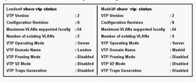
A. The VTP version is not correctly configured.
B. The VTP operating mode is not correctly configured.
C. The VTP domain name is not correctly configured.
D. VTP pruning mode is disabled.
E. VTP V2 mode is disabled.
F. VTP traps generation is disabled.

Answer: C

Explanation:
Both switches must have same domain name configured to exchange vtp messages. first domain name must match so that switches can start exchanging vtp messages, domain name is like a password.

Question 8:
A network administrator is troubleshooting the OSPF configuration of routers R1 and R2. The routers cannot establish an adjacency relationship on their common Ethernet link. The graphic shows the output of the show ip ospf interface e0 command for routers R1 and R2. Based on the information in the graphic, what is the cause of
this problem?
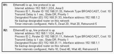
A. The OSPF area is not configured properly.
B. The priority on R1 should be set higher.
C. The cost on R1 should be set higher.
D. The hello and dead timers are not configured properly.
E. A backup designated router needs to be added to the network.
F. The OSPF process ID numbers must match.

Answer: D

Explanation:
Certain parameters within the OSPF hellos must match in order for two routers to become neighbors. They include:
1 Hello/dead timers
2 Area ID
3 Authentication type and password
4 Stub area flag
Hello and dead intervals are not same on both routers.
Question 9:
After the router interfaces shown in the diagram have been configured, it is discovered that hosts in the Branch LAN cannot access the Internet. Further testing reveals additional connectivity issues. What will fix this problem?

A. Change the address of the Branch router LAN interface.
B. Change the address of the Branch router WAN interface.
C. Change the subnet mask of the HQ router LAN interface.
D. Change the address of the HQ router LAN interface.
E. Change the address of the HQ router interface to the Internet.
F. Change the subnet mask of the HQ router interface to the Internet.

Answer: B

Explanation:
The branch router WAN interface is configured with incorrect IP address .
The correct IP will be 192.168.10.86 /30 because HQ WAN IP(192.168.10.85) is on network 192.168.10.84 /30 and the two usable IP's for this network are 192.168.10.85 and 192.168.10.86.

Question 10:
The network administrator wants to upgrade the IOS of a router. The new image requires 64 MB of RAM and 16 MB for storage of the file. Given the output shown in the graphic, which of the following is true?

A. This router meets the requirements for the new image.
B. This router will require a DRAM upgrade to meet the requirements for the new image.
C. This router will require a flash upgrade to meet the requirements for the new image.
D. This router will require an NVRAM upgrade to meet the requirements for the new image.

Answer: B

Explanation:
In above exhibit the flash memory meets the requirement of new IOS image but fails in RAM requirement has it does not have 64 mb installed on the router.

Question 11:
The network administrator has configured NAT as shown in the graphic. Some clients can access the Internet while others cannot. What should the network administrator do to resolve this problem?

A. Configure an IP NAT pool.
B. Properly configure the ACL.
C. Apply the ACL to the S0 interface.
D. Configure another interface with the ip nat outside command.

Answer: B

Explanation:
The NAT translation will only translate 192.168.1.0 /24 because of the access-list 1 statement permit matches only 192.168.1.0 network . Therefore other networks were ignored by NAT.
To correct this problem change the access-list statement with correct wild card mask
access-list 1 permit 192.168.1.0 0.0.255.255


Question 12:
Refer to the network diagram and configuration shown in the graphic. The network at the SOS Company has just been configured for NAT as shown. Initial tests indicate that everything is functioning as intended. However, it is found that a number of hosts cannot access the Internet. What is the problem?
A. The access list is not correct.
B. There are not enough IP addresses available in the NAT address pool.
C. The wrong interface has been configured with the ip nat inside command.
D. The IP address of the Fa0/0 interface is not usable.
E. The S0/1 interface of the ISP router is in the wrong subnet.

Answer: B

Explanation:
The NAT POOL defined above only permits 5 hosts at a time. Because only 5 public IP’s are available for NAT translation i.e only 5 hosts are translated because of one-to-one translation (private to public IP) and therefore remaining hosts are unable to access internet.
To overcome this problem use the NAT OVERLOAD or Port address translation.

Question 13:
Refer to the topology and partial switch command output shown in the graphic. The internetwork shown in the diagram is experiencing connectivity problems. Host A is unable to ping Host B. What needs to be done to enable these hosts to ping each another?
A. The gateway on Host A needs to be changed.
B. The IP address on Host B needs to be reconfigured.
C. VLAN 2 must be named.
D. The Fa0/1 interface on the ET-1 switch must be configured as a trunk port.
E. Switch port Fa0/1 must be moved to a different VLAN.

Answer: D

Explanation:
A trunk port is configured on switch to carry different VLAN information across to layer 3 device for inter-VLAN routing.

Question 14:
Refer to the graphic. Computer 1 is consoled into switch A. Telnet connections and pings run from the command prompt on switch A fail. Which of the following could cause this problem?

A. Switch A is not directly connected to router JAX.
B. Switch A does not have a default gateway assigned.
C. Switch A does not have a CDP entry for switch B or router JAX.
D. Switch A does not have an IP address.
E. Port 1 on switch A should be an access port rather than a trunk port.

Answer: D

Explanation:
IP address needs to be configured for ping test and to manage remotely via telnet on the switch.

Question 15:
Refer to the topology and command output within the exhibit. When hosts on the 172.16.5.0 network attempt to ping the remote server at 192.168.145.27, the message "Reply from 192.168.145.27:TTL expired in transit" is returned. What is the cause of this problem?


A. No static route is configured on the SOHO router to the 192.168.145.0 network.
B. No static route is configured on the ISP router to the 192.168.145.0 network.
C. A routing protocol must be configured to send packets between SOHO and ISP.
D. A routing loop has occurred.

Answer: D

Explanation:
Routing loop occurred because of wrong configuration of default route on both routers .
Each router pointing default routes between each other.

Question 16:
Refer to the exhibit. A network technician is troubleshooting a connectivity problem on R2. The technician enters the show cdp neighbors command at the R2 console. If the network is composed only of Cisco devices, for which devices should entries be displayed?

A. R1
B. SW-B and R1
C. SW-B, R1, and SW-C
D. R3, SW-B, R1, and SW-C
E. SW-A, R3, SW-B, R1, and SW-C
F. Host A, SW-A, R3, SW-B, R1, and SW-C

Answer: B

Explanation:
CDP only gathers information about directly connected neighbor’s information.
Troubleshooting Questions are continued on next blog post @ Troubleshoot 2
Your Ad Here