2 Router Basic Configuration Lab
* DCE
Objective:
In this lab you will configure a simple network to allow two routers to route packets between to remote networks.
Requirements:
* Two Cisco routers with one Ethernet port and one serial port.
* Cisco IOS 10.0 or higher
* One PC for consoling into routers with terminal emulation software
* One serial cable
* One Cisco rollover cable
Setup:
Step 1: Physical Connections Connect the following interfaces:
* Console: Connect your PC/terminal to the console port using a rollover cable and HyperTerminal (9600-8-N-1-no flow)
* Ethernet: Connect Ethernet ports to a hub or a switch using a straight-through cable. Use a cross-over cable if going directly from the PC’s NIC to the Ethernet (AUI) port on the router using a transceiver.
* Serial: If going directly between two routers, don’t forget to connect one port via the DTE cable and the other via the DCE cable.
Step 2: Boot up the routers
Just say “no” to use the setup mode (setup dialogue). The setup mode will only allow you to configure the router with the basic features and not with any advanced features.
If asked if you would like to terminate the auto configuration; say “yes”.
Let the routers finish booting.
Step 3: Host Name and Passwords
Begin your configuration with the hostname and passwords. This is to remind you of what router you are configuring and now's the time to start thinking about router security.
RouterA
router>en router#
router#config t
Enter configuration commands, one per line. End with CNTL/Z.
router(config)#hostname RouterA (sets the router's name)
RouterA(config)#enable secret cisco (Sets the secret password
for the router)
RouterA(config)#line vty 0 4 (there are five concurrent
connections for the telnet ports coming into a Cisco 2500
router. We are setting the login password on all five of them)
RouterA(config-line)#login (This enables the router to require a
login password for a telnet session to the router)
RouterA(config-line)#password cisco (this sets the login
password for all 5 telnet sessions coming into the router as cisco)
RouterA(config-line)#exit
RouterA(config)#^Z (This is the key combination of control+z
which takes you back to the privileged executive mode)
RouterA#
RouterB
router>en
router#
router#config t
Enter configuration commands, one per line. End with CNTL/Z.
router(config)#hostname RouterB (sets the router's name)
RouterB(config)#enable secret cisco (Sets the secret password for the router)
RouterB(config)#line vty 0 4 (there are five concurrent connections for the telnet ports coming into a Cisco 2500 router. We are setting the login password on all five of them)
RouterB(config-line)#login (This enables the router to require a login password for a telnet session to the router)
RouterB(config-line)#password cisco (this sets the login password for all 5 telnet sessions coming into the router as cisco)
RouterB(config-line)#exit
3 RouterB(config)#^Z (This is the key combination of control+z which takes you back to the privileged executive mode)
FYI: Anytime you make a configuration change to a router and you come back to the privileged exec mode you need to save your changes to NVRAM. This ensures that if the router reboots, you won’t loose your changes which are in the running-config which is volatile RAM. The following command(s) saves your changes to the startup-config.
RouterA#copy running-config startup-config
Or
RouterA# copy run start
Or
RouterA#wr me (short for write memory)
Step 4: Adding IP Addresses
Adding IP addresses, is a basic function of configuring routers. Below is an example of configuring both an Ethernet and serial interface. For serial interface with the DCE cable you will need to also add the clocking with the clockrate command. Get the IP addresses from the network diagram.
RouterA
RouterA#config t
Enter configuration commands, one per line. End with CNTL/Z.
RouterA(config)#int e0
RouterA(config-if)#ip address 172.16.12.1 255.255.255.0
RouterA(config-if)# description LAN Network for RouterA
RouterA(config-if)# no shutdown
RouterA(config-if)#int s0
RouterA(config-if)#ip address 172.16.10.1 255.255.255.0
(RouterA will have the serial 0 with the DCE end of the serial cable. The other partner will have serial1 with the DTE end of the serial cable. Check the network diagram to confirm to see who has what interface)
RouterA(config-if)#clockrate 250000 (DCE interface only which is the s0 on RouterA)
RouterA(config-if)#no shutdown
RouterA(config-if)#description Network connection to RouterB
RouterB
RouterB#config t
Enter configuration commands, one per line. End with CNTL/Z.
RouterB(config)#int e0
RouterB(config-if)#ip address 172.16.11.1 255.255.255.0
RouterB(config-if)# description LAN Network for RouterB
RouterB(config-if)# no shutdown
RouterB(config-if)#int s1
RouterB(config-if)#ip address 172.16.10.2 255.255.255.0
RouterB(config-if)#no shutdown
RouterB(config-if)#description Network connection to RouterA
Once both routers are configured properly, you should be able to use the ping command and ping the interface e0 on each of the routers from the neighboring router.
If you do a show ip route on both routers and do not see the directly connected interfaces in the routing table, they are either not configured or they never came up.
Confirm that the IP addressing took and the interfaces came up by using the show ip int and looking at the interfaces' status and ip address configuration.
RouterA# show ip route
RouterA# show ip int
Do this on both routers.
Step 5a: Adding Dynamic Routing: RIP
For this router to participate in a dynamic routing using a dynamic routing protocol like RIP or IGRP, you'll need to enable a routing protocol and advertise the directly connected networks that want advertised.. We only advertise the classful network address, not the subnet mask of the network.
RouterA
RouterA>en
RouterA#config t
Enter configuration commands, one per line. End with CNTL/Z.
RouterA(config)#router RIP
RouterA(config-router)#network 172.16.12.0
RouterB
RouterB>en
RouterB#config t
Enter configuration commands, one per line. End with CNTL/Z.
RouterB(config)#router RIP
RouterB(config-router)#network 172.16.11.0
FYI: We need to advertise the network, not any particular host. An example of that would be enabling RIP on RouterB. We want the other router (RouterA) to know that any packet destined for the network 172.16.11.0 can be sent to RouterB which has a directly connected 5 entry in it’s routing table showing what interface to send the packet to; in this case its e0. If you route to 172.16.11.1, all your every going to route to, is the e0 on RouterB and nothing else.
Test your configuration to ensure that it is configured properly by pinging from router to router. Check your routing table for entries that are preceded by a capital letter "R" to ensure that you are receiving routing updates using RIP. Ensure that your partner has finished configuring his router so that you can receive his updates. No updates, no ping.
Do a show ip protocol to see what routing protocol is configured on the routers.
Step 5b: Adding Dynamic Routing: IGRP IGRP
uses an autonomous system (AS) number or process id. This number must be the same on all routers wanting to share IGRP routing updates or they don’t share. Turn RIP off before you turn on IGRP. For this lab we'll be using an AS number of 100.
RouterA
RouterA>en
RouterA#config t
RouterA(config)#no router rip
RouterA(config)#router igrp 100
RouterA(config-router)#network 172.16.12.0 (again, just the network portion of the IP for your Ethernet network, NO subnet mask)
RouterB
RouterB>en
RouterB#config t
Enter configuration commands, one per line. End with CNTL/Z. RouterB(config)#no router rip
RouterB(config)#router igrp 100
RouterB(config-router)#network 172.16.11.0 (again, your Ethernet network IP NO Subnet Address)
Step 6: Adding Default Routes
Good candidates for default routes are routers which are known as the boundary router. This is a router which is normally part of a stub network. Inside the stub network, the routers may be participating in a dynamic routing using a protocol like RIP, but only a static default route is needed to connect the stub network to the Internet.
RouterA
RouterA>en
RouterA#config t
RouterA(config)#ip route 0.0.0.0 0.0.0.0 172.16.10.2
RouterB
RouterB>en
RouterB#config t
RouterB(config)#ip route 0.0.0.0 0.0.0.0 172.16.10.1
Step 7: Adding Static Routes
A static route can be used for different reasons. One reason may be for a router to connect to another router in a lab. You'll need to turn off all routing protocols before you configure the router for static routing.
RouterA
RouterA>en
RouterA#config t
RouterA(config)#no router igrp 100
RouterA(config)#ip route 172.16.11.0 255.255.255.0 172.16.10.2
What we are saying here is: For RouterA to route to the network 172.16.11.0, go to the next hop interface which is the serial1 (172.16.10.2) attached to RouterB. Since RouterB knows about the directed connected Ethernet network of 172.16.11.0, it will have route for it in its routing table proceeded by the letter "C". (See next example)
RouterB#sh ip route
(Output omitted)
172.16.0.0/24 is subnetted, 1 subnets
C 172.16.0.0 is directly connected, Ethernet0
RouterB#
RouterB
RouterB>en
RouterB#
RouterB#config t
RouterB(config)#no router igrp 100
RouterB(config)#ip route 172.16.12.0 255.255.255.0 172.16.10.1
Step 8: Testing and Monitoring
At this point it is a good idea to start testing your network using various commands. Perform the following on both routers.
RouterA# show ip route
RouterA# show ip interface brief (This command shows the IP and status of all interface)
RouterA# show controller s0 (Shows whether or not the serial cable is DCE or DTE.)
RouterA# ping ip-address
RouterA# trace ip-address
RouterA# debug ip rip (Remember to turn debug off when done, use undebug all, no debug all or un all)
RouterA# terminal monitor (for using debug from a telnet
session, otherwise debug output will go to the console. Caution: This will cause the debug output to go to all telnet sessions on the router.)
Show commands
RouterA# terminal no monitor(To turn off monitoring during a telnet session.)
RouterA# show cdp neighbors
RouterA# show ip protocols
RouterA# #show version
RouterA# #show flash
RouterA# show ip route (shows the routing table)
RouterA# show memory
RouterA# show stacks
RouterA# show buffers
RouterA# show arp
RouterA# show processes
RouterA# show processes cpu
RouterA# show tech-support
Step 9: Finishing up
Once you have your routers up and working you may wish to run some commands to make working on Cisco routers easier and to stop some of the default annoying behavior of Cisco routers.
RouterA(config)# ip host RouterB 172.16.10.2 (This configures a host table entry for the name RouterB. So instead of having to remember the IP of RouterB to ping it, you can now ping it using its name, RouterB. It's the same as using a hosts file on a computer. If you just type in RouterB and hit enter, the router will assume you’re wanting to telnet into RouterB using port 23) RouterA(config)# no ip domain-lookup (When there is no DNS server and you miss spell a single word command, it will try to do a DNS lookup using a broadcast address of 255.255.255.255. To stop this lookup of a non-existent DNS server, we can turn off the DNS lookup capability using this command.)
RouterA(config)# banner motd #!!!!Warning! Authorized Access Only!!!!# (This message will be seen by anyone trying to logon to your router. The # sign is known as a delimiting character and is used to identify the text portion of the MOTD. Notice that the actual message starts and ends with the delimiting character)
RouterA(config)# no service-config (When you reboot a Cisco router, the default behavior is to try and find a configuration file on the network using a number of methods over a broadcast address of 255.255.255.255. To stop this annoying behavior, Use this command.)
RouterA(config)#no logging console (Each time you leave one level of the router and return to the previous level or bring an interface up, you get a read out on the console screen. If you get busy typing and configuring the router this can be distracting and annoying. Use this command to stop the logging of messages to the console screen.)
And don’t forget to…
RouterA# show running-config
RouterA# copy running-config startup-config
Miscellaneous
RouterA#? (the question mark can be used by itself or follow at the end of any partial command line to get the next part of the command syntax)
To have the router CLI finish typing a command for you, just type out a partial command and hit the TAB key. An example would be typing out copy ru and hitting the TAB key. The router CLI with finish the command as copy running-configuration. Now if you add st to that and hit the tab key again, the CLI will add to your last command startup-configuration, making your entire command copy running-configuration startup-configuration. This works because there is only one command the begins with copy ru.
Editing Commands
Control-A: Moves to the beginning of the command line.
Control-E: Moves to the end of the command line.
Esc-B: Moves back one word.
Control F: Moves forward one character.
Control-B: Move back one character.
Esc F: Moves forward one word.
History Commands
Control P or up arrow key - Recalls last (previous command.)
Control N or down arrow key - Recalls most recent command
Tab key: completes the entry.
RouterA# show history
RouterA# terminal history
RouterA# terminal editing
RouterA# no terminal editing
FYI: This lab was designed to show you how to configure basic routing between two routers. If you would like to ping from one PC on one network (RouterA) to another PC on the other network (RouterB), you would need to configure the PC on each network with a host IP that belonged to the Ethernet network IP of each router. An example of that would be that the first available IP for a PC on the Ethernet network of RouterB would be 172.16.11.2. We know that the ".1" is already in use for the e0 interface on RouterB. The subnet mask for the PC would have to be the same as the rest of the network; 255.255.0.0 and the default gateway for the PC would be the e0 that connects the LAN to RouterB.
So if a PC needs to find something that is not local or located on its LAN, the DFGW will take the request to the router by way of the Ethernet Interface that connects the LAN to the Router. An example of that would be, if you ping a PC located on the Ethernet network of RouterB from RouterA’s LAN, the return echo from the PC has to know how to get back to the network on RouterA from which it came. Since the Ethernet network path on RouterA is known to RouterB through a routing table entry, the DFGW on the PC will take the unknown request for the return trip of the packet from the PC and send it to RouterB which will know what to do with it. No default Gateway in the TCP/IP properties of the PC and the packet will just time out and the ping attempt will be unsuccessful. Chances are the ping did reach the PC but the return echo did not know how to find a way back.
End of Lab
Basic Router Configuration Lab NoAnswers
Objective:
In this lab you will configure a simple network to allow two routers to route packets between to remote networks.
Requirements:
* Two Cisco routers with one Ethernet port and one serial port.
* Cisco IOS 10.0 or higher
* One PC for consoling into routers with terminal emulation software
* One serial cable
* One Cisco rollover cable
Setup:
Step 1: Physical Connections
Configure a console session to your router(s) from your PC.
Step 2: Boot up the routers
Do not use the setup mode (setup dialogue) or auto configuration to configure the router. Let the routers finish booting.
Step 3: Host Name and Passwords
Begin your configuration with the hostnames and passwords for both routers.
Configure RouterA and RouterB with their correct hostnames. Configure all telnet sessions on both routers with the password of cisco Exit back to the privileged mode and save your current configuration
Step 4: Adding IP Addresses
Configure the interfaces on both routers with the IPs as per the network diagram. Set a description on all interface. Set the clockrate on the DCE end of the serial cable with a clockrate of 250000. Ensure the interfaces come up.
Step 5a: Adding Dynamic Routing: RIP
Configure both routers for dynamic routing using the routing protocol RIP. Advertise the appropriate networks on both routers.
Check both routers to see if they are receiving RIP routing updates from each other. Ensure connectivity between the routers by using the ping command. Remove RIP before starting step 5b.
Step 5b: Adding Dynamic Routing:
IGRP Configure both routers to use the routing protocol IGRP. Configure both routers to use the same AS number. Advertise the appropriate networks on both routers.
Check both routers to see if they are receiving IGRP routing updates from each other. Check to see what routing protocol the routers are using. Ensure connectivity between the routers by using the ping command. Remove IGRP before starting step 6.
Step 6: Adding Default Routes
Configure both routers with a default route to each other. Use the neighboring router as a smart gateway of last resort.
Check to ensure that the routers have a default route.
Ensure connectivity between the routers by using the ping command and pinging the interface e0 on each router.
Step 7: Adding Static Routes
Configure both routers with static routes to each routers remote network. Tell the routers how to find the path to each others Ethernet network.
Check to ensure that the routers have a static route.
Ensure connectivity between the routers by using the ping command and pinging the interface e0 on each router.
Step 8: Optimize the router performance.
Create a host table entry on each router to be able to ping the name of the router in lieu of the IP address.
Configure both routers to turn off ip domain-lookup so they do not try and use a DNS server.
Configure a MOTD on each router that warns of authorized access only.
Configure both router not to look for a network configuration when they startup.
Disable logging to the console screen on both routers.
Step 9:
Configure your PC(s) for connectivity on the network.
Ping from the PC connected on RouterA's Ethernet 0 network to the PC on the Ethernet 0 of RouterB. If you only have one PC, ping the interface Ethernet 0 on the either router.
End of Lab
Tuesday, September 30, 2008

Three Router Static Route Lab
Objective
In this lab, you will configure static routes between all three routers. This will allow your routers to route packets so that all routers and all hosts will be able to reach (ping) each other. Once your configuration is complete, you will use basic techniques to test your network’s connectivity.
Scenario
Three separate classful networks need routing between them and their subnets.
Questions:
* What are the different classful networks?
1. ________________
2. ________________
3. ________________
4. ________________
5. ________________
* Are there any subnets? If so, what are they?
1. _______________
2. _______________
3. _______________
4. _______________
5. _______________
Setup
* Configure the cabling as shown in the network diagram
* If the routers have a startup-config, erase it and perform a reload of the routers.
* Important! Configure the routers to include hostnames and the proper interface commands including IP addresses, subnet masks, etc. Each router should be able to ping the interface of the adjacent (neighboring) router and the host on its LAN (Ethernet) interface. Test and troubleshoot as necessary. Use the context sensitive help, previous labs, your books and /or handouts and if your still having problems ask your partner or ask the instructor for assistance.
Step 1 – Configuring Static Routes
On each router configure a separate and specific static route for each network or subnet. You do not need to configure static routes for the router’s directly connected network(s) because like a host, by configuring the IP address and subnet mask on an interface tells the router that it belongs to that network/subnet.
Router1
* Router1(config)# ip route 172.16.3.0 255.255.255.0 172.16.2.1
* Router1(config)# ip route 192.168.2.0 255.255.255.0 192.168.1.1
Router2
* Router2(config)# ip route 172.16.1.0 255.255.255.0 172.16.2.2
* Router2(config)# ip route 192.168.1.0 255.255.255.0 172.16.2.2
* Router2(config)# ip route 192.168.2.0 255.255.255.0 172.16.2.2
Router3
* Router3(config)# ip route 172.16.1.0 255.255.255.0 192.168.1.2
* Router3(config)# ip route 172.16.2.0 255.255.255.0 192.168.1.2
* Router3(config)# ip route 172.16.3.0 255.255.255.0 192.168.1.2
Verify and Validate:
* All hosts and all routers should be able to ping every interface in the network.
* Do a “show running-config” and notice the static routes that you entered.
* Router# show ip route
o What routes to networks do you see?
o Which routes are static and which routes are directly connected?
o What is the administrative distance for a static route?
o What is the administrative distance for a directly connected network?
Questions:
* How does the next-hop-ip-address help with the routing process?
_____________________________________________.
* Does it give the entire route, i.e., subnet mask?
_________________
* What is it actually doing regarding the routing of the packet?
____________________________________________
* How does a packet get from Host 2 to Host 3?
____________________________________________
____________________________________________
____________________________________________
* Instead of a next-hop-ip-address, what else could you have used?
____________________________________________.
* What would you need to do if you added new networks or deleted/modified existing networks?
____________________________________________
____________________________________________
____________________________________________
* Is there any way to summarize several static routes to multiple subnets into a single static route?
_____________________________________________
_____________________________________________
_____________________________________________
Outputs
Router2#show ip route
(Output omitted)
Gateway of last resort is not set
172.16.0.0/24 is subnetted, 3 subnets
S 172.16.1.0 [1/0] via 172.16.2.2
C 172.16.2.0 is directly connected, Serial0
C 172.16.3.0 is directly connected, Ethernet0
S 192.168.1.0/24 [1/0] via 172.16.2.2
S 192.168.2.0/24 [1/0] via 172.16.2.2
Router1#show ip route
(output omitted)
Gateway of last resort is not set
172.16.0.0/24 is subnetted, 3 subnets
C 172.16.1.0 is directly connected, Ethernet0
C 172.16.2.0 is directly connected, Serial0
S 172.16.3.0 [1/0] via 172.16.2.1
C 192.168.1.0/24 is directly connected, Serial1
S 192.168.2.0/24 [1/0] via 192.168.1.1
Router3#show ip route
(Output omitted)
Gateway of last resort is not set
172.16.0.0/24 is subnetted, 3 subnets
S 172.16.1.0 [1/0] via 192.168.1.2
S 172.16.2.0 [1/0] via 192.168.1.2
S 172.16.3.0 [1/0] via 192.168.1.2
C 192.168.1.0/24 is directly connected, Serial0
C 192.168.2.0/24 is directly connected, Ethernet0
Step 2 – Configuring Summary Static Routes
The configuration of the routers in Step 1 works just great and is a valid way to configure routing on these networks. Earlier, we noticed that the network 172.16.0.0 is divided into several subnets. The Router3 router does not really need separate static routes for each subnet, since all of the 172.16.0.0 subnets can be reached via the same next-hop-ip-address, i.e. Router1. Let’s reconfigure the static routes on Router3 so that it only uses a single static route to reach all of the 172.16.0.0 subnets.
Router1
* No changes
Router2
* No changes
Router3
* First, remove the current static routes:
* Router3(config)# no ip route 172.16.1.0 255.255.255.0 192.168.1.2
* Router3(config)# no ip route 172.16.2.0 255.255.255.0 192.168.1.2
* Router3(config)# no ip route 172.16.3.0 255.255.255.0 192.168.1.2
* Now, add the new summary static route:
* Router3(config)# ip route 172.16.0.0 255.255.0.0 192.168.1.2
Verify and Validate:
* All hosts and all routers should be able to ping every interface in the network.
* Do a “show running-config” and notice the static routes that you entered.
* Router3# show ip route
o What routes to networks do you now see?
Questions:
* What made this new summary static route work for all subnets?
_____________________________________________________
_____________________________________________________
_____________________________________________________
* Why is a single summary static route an advantage regarding the size of the routing table?
_____________________________________________________
_____________________________________________________
_____________________________________________________
* Why is a single summary static route an advantage regarding future changes to the 172.16.0.0 network?
_____________________________________________________
_____________________________________________________
_____________________________________________________
Outputs
Router3#show ip route
(Output omitted)
Gateway of last resort is not set
S 172.16.0.0/16 [1/0] via 192.168.1.2
C 192.168.1.0/24 is directly connected, Serial0
C 192.168.2.0/24 is directly connected, Ethernet0
Step 3 – Configuring Default Static Routes
Both Step 1 and Step 2 are acceptable ways to configure routing for these networks. We notice that the 172.16.3.0/24 and the 192.168.2.0/24 networks are “stub networks,” meaning that there is only one way out (both via Router1).
Router1
* No changes
Router2
* First, remove the current static routes:
* Router2(config)# no ip route 172.16.1.0 255.255.255.0 172.16.2.2
* Router2(config)# no ip route 192.168.1.0 255.255.255.0 172.16.2.2
* Router2(config)# no ip route 192.168.2.0 255.255.255.0 172.16.2.2
* Now, add the new default static route:
* Router2(config)# ip route 0.0.0.0 0.0.0.0 172.16.2.2
Router3
* First, remove the current static routes:
* Router3(config)# no ip route 172.16.0.0 255.255.0.0 192.168.1.2
* Now, add the new default static route:
* Router3(config)# ip route 0.0.0.0 0.0.0.0 192.168.1.2
Verify and Validate:
* All hosts and all routers should be able to ping every interface in the network.
* Do a “show running-config” and notice the static routes that you entered.
* Router2# show ip route
o What routes to networks do you now see?
* Router3# show ip route
o What routes to networks do you now see?
Questions:
* Do you think static routes are still used even with dynamic routing (RIP, OSPF, etc.)?
_______________. Hint: Think about the administrative distance.
* Do you think default static routes are still used even with dynamic routing (RIP, OSPF, etc.)?
_______________.
* What is the disadvantage of doing this? How would a default static route be properly used in a real world network? (How would a company’s network use a default route when connecting to the Internet?)
________________________________________
________________________________________
________________________________________
Outputs
Router3#show ip route
(Output omitted)
Gateway of last resort is 192.168.1.2 to network 0.0.0.0
C 192.168.1.0/24 is directly connected, Serial0
C 192.168.2.0/24 is directly connected, Ethernet0
S* 0.0.0.0/0 [1/0] via 192.168.1.2
Save your current configuration to NVRAM.
End of Lab
Cisco 2950 Switch VLAN & Trunking Lab
LAB CATALYST 2950 SWITCH CONFIGURATION
Prerequisite Setup – You will configure an Ethernet router with an IP address of 197.10.1.1 255.255.255.0 to E0. You will connectE0 on your Router to E0/1 on Switch1. You will then connect Switch 1 and 2 together via port FA0/12 on each. Finally, you will connect a PC with an IP of 197.10.1.2 255.255.255.0 default gateway 197.10.1.1 to E0/1 via Switch2.
1. In this lab, you will configure basic IOS commands on switch1 and switch2 which are Catalyst 2950 switches.
2. HyperTerminal into Switch1 (Catalyst 2950). Press enter to get into the user prompt mode.
Enter enable to get into privileged mode.
Type ? to see a list of privileged mode commands. Enter disable to go back to user mode.
enter
> enable
# ?
# disable
>
3. On switch1, go into privileged mode and then into global configuration mode. Assign Switch1 a host name of 2950sw1.
Use exit or ctrl-z to get out of configuration mode.
> enable
# configure terminal
(config)# hostname 2950sw1
2950sw1(config)# exit
2950sw1#
4. On switch1, type show running-config to see the active configuration.
2950sw1# show running-config
5. On switch1, type copy running-config startup-config to save the active configuration to NVRAM. Display the saved configuration in NVRAM
with the show startup-config command.
2950sw1# copy running-config startup-config
2950sw1# show startup-config
6. On switch1, erase the saved configuration and reload the box.
2950sw1# erase startup-config
2950sw1# reload
7. On switch1, go into privileged mode and then into global configuration mode. Reassign the switch a hostname of 2950sw1 and an enable pass of ‘cisco’ (unencrypted).
Assign the switch an IP address of 197.10.1.99 with a subnet mask of 255.255.255.0.
Assign the switch a default gateway of 197.10.1.1 (your router’s Ethernet address).
> enable
# configure terminal
(config)# hostname 2950sw1
2950sw1(config)# enable password cisco
2950sw1(config)# interface vlan1
2950sw1(config-if)# ip address 197.10.1.99 255.255.255.0
2950sw1(config-if)# no shutdown
2950sw1(config-if)# exit
2950sw1(config)# ip default-gateway 197.10.1.1
8. On switch1, issue the show interface vlan1 command to verify that the IP address, mask, and default gateway are correct.
2950sw1# show interface vlan1
9. On switch1, issue the show interfaces command.
2950sw1# show interfaces
10. HyperTerminal into Switch 2 (Catalyst 2950). Configure it with a hostname of 2950sw2 and an enable password of cisco
(the enable password should be encrypted when displaying the configuration file). Assign an IP address of 197.10.1.100/24 and a default gatew
of 197.10.1.1.
> enable
# configure terminal
(config)# hostname 2950sw2
2950sw2(config)# enable secret cisco
2950sw2(config)# interface vlan1
2950sw2(config-if)# ip address 197.10.1.100 255.255.255.0
2950sw2(config-if)# no shutdown
2950sw2(config-if)# exit
2950sw2(config)# ip default-gateway 197.10.1.1
On switch2, issue the show version command.
2950sw2# show version
11. On switch4, issue the show spantree command.
2950sw4# show spantree
12. On switch2, issue the show mac-address-table command. This shows which devices are attached to which switch ports.
2950sw4# show mac-address-table
13. On switch2, permanently assign a device with MAC address 4444-4444-4444 to port fa0/5. Issue the show mac-address-table command to verify the device is in the table as a permanent entry.
2950sw2(config)# mac-address-table static 4444-4444-4444 vlan 1 int fa0/5
2950sw2(config)# exit
2950sw2# show mac-address-table
14. On switch2, configure port security for port fa0/9. The switch will ‘sticky-learn’ the MAC address of the device connected to port fa0/9 and will only allow that device to connect to the port in the future.
2950sw2(config)# interface fa0/9
2950sw2(config-if)# switchport port-security
2950sw2(config-if)# switchport port-security maximum 1
LAB VLANs and TRUNKING (Catalyst 2950 Switches)
1. In this lab, you will set up VLANs on switch1 and switch2 (Catalyst 2950 switches) and test them by pinging between your router and PC.
Your Router is connected to e0/1 on switch1 and the PC is connected to e0/1 on switch2.
Switch1 and switch2 are interconnected through their fa0/12 Fast Ethernet ports.
2. On the PC using winipcfg, configure an IP address of 197.10.1.2/24 and a default gateway of 197.10.1.1.
c:> winipcfg
3. Verify you can presently ping between the PC and your router. If you cannot ping successfully, check that your router’s Ethernet0 IP address is 197.10.1
and that the interface is enabled. Also, using the winipcfg utility, check that PC has a configured IP address of 197.10.1.2/24.
c:> ping 197.10.1.1
4. On switch1 and switch2, issue the show vlan command. You should note that, by default, all switch ports are in VLAN1. Because your router, PC and the switch-to-switch link are all in VLAN1, you should be able to ping between the PC2 and the router.
2950swx# show vlan
5. On switch1 and switch2, set up a VTP domain called ciscokits. Verify it has been created with the show vtp status command.
2950swx# vlan database
2950swx(vlan)# vtp domain ciscokits
2950swx(vlan)# ctrl-z
2950swx# show vtp status
6. On switch1 and switch2, create VLAN 20, calling it 2950vlan. Issue the show vlan command to verify it was successfully created.
2950swx# vlan database
2950swx(vlan)# vlan 20 name 2950vlan
2950swx(vlan)# exit
2950swx# show vlan
7. On switch1 and switch2, assign the fa0/1 ports to the new VLAN you created. Your Router and PC are attached to these ports. Issue the show vlan command on both switches to verify these ports have been moved to VLAN20. .
2950swx(config)# interface fa0/1
2950swx(config-if)# switchport access vlan 20
2950swx(config-if)# ctrl-z
2950swx# show vlan
8. Now that both your router and PC are in VLAN20, try to ping from the PC to the router. It should fail.
c:> ping 197.10.1.1
9. Make the link between switch1 and switch2 a trunk line capable of carrying traffic for any VLAN.
Use the show interface fa0/12 switchport command to verify trunking is enabled on port fa0/12 on both switches.
2950swx(config)# interface fa0/12
2950swx(config-if)# switchport mode trunk
2950swx(config-if)# ctrl-z
2950swx# show interface fa0/12 switchport
10. Now ping between the PC and the router. The pings should succeed because both devices are in the same VLAN and the inter-switch link is a trunk line capable of carrying traffic for any VLAN.
c:> ping 197.10.1.1
3 WAY TO SETUP ROUTER WITH FRAME RELAY
Hardware Requirement:
* 1 Router with 2 Serials
* 2 Router with 1 Serial
* 2 DTE/DCE Serial Cables
* IOS Version 11.x or later
CONFIGURATION OF FRAME RELAY ROUTER
Router>enable
Router#conf t
Router(config)#hostname FR
FR(config)#enable password cisco
FR(config)#frame-relay switching
FR(config-if)#int s0
FR(config-if)# no ip address
FR(config-if)# encapsulation frame-relay
FR(config-if)# clockrate 64000
FR(config-if)# frame-relay lmi-type ansi
FR(config-if)# frame-relay intf-type dce
FR(config-if)# frame-relay route 100 interface Serial1 200
FR(config-if)# no shut
FR(config-if)#int s1
FR(config-if)# no ip address
FR(config-if)# encapsulation frame-relay
FR(config-if)# clockrate 64000
FR(config-if)# frame-relay lmi-type ansi
FR(config-if)# frame-relay intf-type dce
FR(config-if)# frame-relay route 200 interface Serial0 100
FR(config-if)# no shut
FR(config-line)#line vty 0 4
FR(config-line)# password cisco
FR(config-line)# login
FR(config-line)#end
FR#write
CONFIGURATION OF ROUTER 1
Router>Enable
Router#conf t
Router(config)#hostname R1
R1(config)#enable password cisco
R1(config-line)#line vty 0 4
R1(config-line)# password cisco
R1(config-line)# login
R1(config)#int loopback 0
R1(config-if)#ip add 1.1.1.1 255.255.255.255
R1(config-if)#no shut
R1(config-if)#int s0
R1(config-if)# encapsulation frame-relay
R1(config-if)# frame-relay lmi-type ansi
R1(config-if)# no shut
R1(config)#int Serial0.1 point-to-point
R1(config-subif)# ip address 192.168.1.1 255.255.255.0
R1(config-subif)# frame-relay interface-dlci 100
R1(config)#ip route 0.0.0.0 0.0.0.0 192.168.1.2
R1#write
CONFIGURATION OF ROUTER 2
Router>Enable
Router#conf t
Router(config)#hostname R2
R2(config)#enable password cisco
R2(config-line)#line vty 0 4
R2(config-line)# password cisco
R2(config-line)# login
R2(config)#int loopback 0
R2(config-if)#ip add 2.2.2.2 255.255.255.255
R2(config-if)#no shut
R2(config)#int s0
R2(config-if)# no ip address
R2(config-if)# encapsulation frame-relay
R2(config-if)# frame-relay lmi-type ansi
R2(config-if)# no shut
R2(config-if)#interface Serial0.1 point-to-point
R2(config-subif)# ip address 192.168.1.2 255.255.255.0
R2(config-subif)# frame-relay interface-dlci 200
R2(config-if)#no ip classless
R2(config)#ip route 0.0.0.0 0.0.0.0 192.168.1.1
R2#write
TEST CONNECTIVITY OF FRAME RELAY ROUTER
FR#sho frame route
Input Intf Input Dlci Output Intf Output Dlci Status
Serial0 100 Serial1 200 active
Serial1 200 Serial0 100 active
FR#
TESTING CONNECTIVITY ROUTER 1
R1#ping 192.168.1.2
Type escape sequence to abort.
Sending 5, 100-byte ICMP Echos to 192.168.1.2, timeout is 2 seconds:
!!!!!
Success rate is 100 percent (5/5), round-trip min/avg/max = 32/32/36
ms
R1#ping 192.168.1.1
Type escape sequence to abort.
Sending 5, 100-byte ICMP Echos to 192.168.1.1, timeout is 2 seconds:
!!!!!
Success rate is 100 percent (5/5), round-trip min/avg/max = 60/61/64
ms
R1#show frame-relay map
Serial0.1 (up): point-to-point dlci, dlci 100(0x64,0x1840), broadcast
status defined, active
R1#sho ip route
(Output omitted)
Gateway of last resort is 192.168.1.2 to network 0.0.0.0
1.0.0.0/32 is subnetted, 1 subnets
C 1.1.1.1 is directly connected, Loopback0
C 192.168.1.0/24 is directly connected, Serial0.1
S* 0.0.0.0/0 [1/0] via 192.168.1.2
R1#
TESTING CONNECTIVITY ROUTER 2
R2#ping 192.168.1.1
Type escape sequence to abort.
Sending 5, 100-byte ICMP Echos to 192.168.1.1, timeout is 2 seconds:
!!!!!
Success rate is 100 percent (5/5), round-trip min/avg/max = 32/32/36 ms
R2#ping 192.168.1.2
Type escape sequence to abort.
Sending 5, 100-byte ICMP Echos to 192.168.1.2, timeout is 2 seconds:
!!!!!
Success rate is 100 percent (5/5), round-trip min/avg/max = 60/62/68 ms
R2#sho frame map
Serial0.1 (up): point-to-point dlci, dlci 200(0xC8,0x3080), broadcast
status defined, active
R2#sho ip route
(Output omitted)
Gateway of last resort is 192.168.1.1 to network 0.0.0.0
2.0.0.0/32 is subnetted, 1 subnets
C 2.2.2.2 is directly connected, Loopback0
C 192.168.1.0/24 is directly connected, Serial0.1
S* 0.0.0.0/0 [1/0] via 192.168.1.1
R2#
Frame Relay Monitoring
Router# show interface or show interface serial are the most common commands which show a wide variety of information including showing you the DLCI used for LMI. When monitoring Frame Relay information on the router, a number of items are typically monitored including DLCI and LMI.
Router# debug frame-relay LMI command that you would use to monitor LMI information
Frame Relay Troubleshooting
If a Frame-Relay DLCI attains a state other than “active” meaning inactive or deleted, you can check the Frame-Relay configuration to make sure its configuration matches the configuration of the router acting as the Frame-Relay DTE device.
Router# show frame-relay pvc - can be used to verify that the Frame-Relay PVCs are active and operational
Router# show frame-relay route - can be used to get a listing of the status of all the PVC’s
Router# show frame-relay map - can be used to verify that inverse ARP has successfully mapped remote network layer addresses to the appropriate DLCI.
Sunday, September 28, 2008
CCNP-642-801- Lab tutorial
Network Discovery-Router 1
Network Discovery-Router 2
Network Discovery-Router 3
Configuring Single Area OSPF 1
Configuring Single Area OSPF 2
Config OSPF NBMA Environment
Config OSPF NBMA Network
Config Multi-area OSPF Network
Verify MultiMulti-area OSPF Network
Stub Areas
Totally Stubby Areas
Not So Stubby Areas-Creation
Virtual Links Setup 1
Virtual Links Setup 2
IP Helper-Adress Command
Redundant EIGRP Routers A-C
Redundant EIGRP Routers D&E
Redundant EIGRP Testing
EIGRP Across Frame-Relay I
EIGRP Across Frame-Relay II
Configuring BGP
BGP Route Reflection AS 100
IGRP integration
Directed-Broadcast Handling
Configuring Basic BGP
Creating a BGP Router Reflector
Configuring BGP Connection Weight
Modifying Redist Admin Distances
Redistribution with Router Filters
Router Map Creation
Link download
Saturday, September 27, 2008
CCNA Lab- List of tutorial in flash
List of tutorial will be updated in this post
CCNA Lab: Initial Switch Configuration
Cisco Lab: Loading the 2600 IOS
CCNA Lab: Copy from the TFTP Server
CCNA Lab: Copy to TFTP Server
CCNA Lab: Copy to NVRAM
CCNA Lab: IGRP Routing
CCNA Lab: RIP Routing
CCNA Lab: Password Recovery
CCNA Lab: Router Configuration
CCNA Lab: Saving The Backup Configuration
CCNA Lab: Initial Router Configuration
CCNA Lab: Clearing The Backup Config
CCNA Lab: Telnetting to a Remote Router
CCNA Lab: Examine a Router
CCNA Lab: Console Login
CCNA Lab: IPX Access List Security
CCNA Lab: IPX SAP Filtering
CCNA Lab: IPX Router Config
CCNA Lab: Limiting VTY Access
CCNA Lab: Creating Standard Access Lists
Tuesday, September 23, 2008
CCNA-V4-S4-Final
Result = 94%
1. A technician has been asked to run Cisco SDM one-step lockdown on the router of a customer. What will be the result of this process?
1. A technician has been asked to run Cisco SDM one-step lockdown on the router of a customer. What will be the result of this process?
Traffic is only forwarded from SDM-trusted Cisco routers.
Security testing is performed and the results are saved as a text file stored in NVRAM.
The router is tested for potential security problems and any necessary changes are made.
All traffic entering the router is quarantined and checked for viruses before being forwarded.
2. Refer to the exhibit. A network administrator is trying to configure a router to use SDM but it is not functioning correctly. What could be the problem?
The username and password are not configured correctly.
The authentication method is not configured correctly.
The HTTP timeout policy is not configured correctly.
The vtys are not configured correctly.
3. Refer to the exhibit. How is the TCP/IP configuration information specified by the default-router and dns-server commands made available?
The TCP/IP information is forwarded to a 10.0.1.3 to be supplied to DHCP clients.
The TCP/IP information is used by DHCP clients that are configured to request a configuration from R1.
The TCP/IP information is supplied to any DHCP client on the network connected to the FastEthernet 0/0 interface of R1.
The TCP/IP information is applied to each packet that enters R1 through the FastEthernet 0/0 interface that are hosts on the 10.0.1.0 /24 network except packets from addresses 10.0.1.2, 10.0.1.16, and 10.0.1.254.
4. What is a major characteristic of a worm?
malicious software that copies itself into other executable programs
tricks users into running the infected software
a set of computer instructions that lies dormant until triggered by a specific event
exploits vulnerabilities with the intent of propagating itself across a network
5. Refer to the exhibit. What can be concluded from the exhibited output of the debug ip nat command?
The 10.1.1.225 host is exchanging packets with the 192.168.0.10 host.
The native 10.1.200.254 address is being translated to 192.168.0.10.
The 192.168.0.0/24 network is the inside network.
Port address translation is in effect.
6. A technician is talking to a colleague at a rival company and comparing DSL transfer rates between the two companies. Both companies are in the same city, use the same service provider, and have the same rate/service plan. What is the explanation for why Company A reports higher download speeds than Company B?
Company B has a higher volume of POTS voice traffic than Company A.
Company B shares the conection to the DSLAM with more clients than Company A.
Company A only uses microfilters on branch locations.
Company A is closer to the service provider.
7. Refer to the exhibit. Which statement correctly describes how Router1 processes an FTP request entering interface s0/0/0, destined for an FTP server at IP address 192.168.1.5?
It matches the incoming packet to the access-list 201 permit any any statement and allows the packet into the router.
It reaches the end of ACL 101 without matching a condition and drops the packet because there is no access-list 101 permit any any statement.
It matches the incoming packet to the access-list 101 permit ip any 192.168.1.0 0.0.0.255 statement, ignores the remaining statements in ACL 101, and allows the packet into the router.
It matches the incoming packet to the access-list 201 deny icmp 192.168.1.0 0.0.0.255 any statement, continues comparing the packet to the remaining statements in ACL 201 to ensure that no subsequent statements allow FTP, and then drops the packet.
8. Refer to the exhibit. Which two conclusions can be drawn from the output shown? (Choose two.)
This network is experiencing congestion.
The Frame Relay connection is in the process of negotiation.
Data is not flowing in this network.
The network is discarding eligible packets.
The DLCI is globally significant.
9. A system administrator must provide Internet connectivity for ten hosts in a small remote office. The ISP has assigned two public IP addresses to this remote office. How can the system administrator configure the router to provide Internet access to all ten users at the same time?
Configure DHCP and static NAT.
Configure dynamic NAT for ten users.
Configure static NAT for all ten users.
Configure dynamic NAT with overload.
10. Refer to the exhibit. Company ABC expanded its business and recently opened a new branch office in another country. IPv6 addresses have been used for the company network. The data servers Server1 and Server2 run applications which require end-to-end functionality, with unmodified packets that are forwarded from the source to the destination. The edge routers R1 and R2 support dual stack configuration. What solution should be deployed at the edge of the company network in order to successfully interconnect both offices?
a new WAN service supporting only IPv6
NAT overload to map inside IPv6 addresses to outside IPv4 address
a manually configured IPv6 tunnel between the edge routers R1 and R2
static NAT to map inside IPv6 addresses of the servers to an outside IPv4 address and dynamic NAT for the rest of the inside IPv6 addresses
11. Refer to the exhibit. You are a network administrator who has been tasked with completing the Frame Relay topology that interconnects two remote sites. How should the point-to-point subinterfaces be configured on HQ to complete the topology?
HQ(config-subif)#frame-relay interface-dlci 103 on Serial 0/0/0.1
HQ(config-subif)#frame-relay interface-dlci 203 on Serial 0/0/0.2
HQ(config-subif)#frame-relay interface-dlci 301 on Serial 0/0/0.1
HQ(config-subif)# frame-relay interface-dlci 302 on Serial 0/0/0.2
HQ(config-subif)#frame-relay map ip 172.16.1.1 103 broadcast on Serial 0/0/0.1
HQ(config-subif)#frame-relay map ip 172.16.2.2 203 broadcast on Serial 0/0/0.2
HQ(config-subif)#frame-relay map ip 172.16.1.1 301 broadcast on Serial 0/0/0.1
HQ(config-subif)#frame-relay map ip 172.16.2.2 302 broadcast on Serial 0/0/0.2
12. An established company has recently transitioned from outsourced LAN support to a completely in-house staff. The outsourcing company is no longer in business, so no records are available. There are many user complaints about application speed and availability. What two considerations apply to this situation? (Choose two.)
A network utilization baseline should quickly reveal application availability.
A period of 24 to 48 hours should provide a sufficient baseline to track normal network activity.
It is easier to start with monitoring all available data inputs on application servers, and then fine-tune to fewer variables along the way.
The initial baseline results have little relevance to current values after the network has been modified or grown in usage.
When it is practical, network administrators should attempt to automate the collection of performance data and stay away from manual collection.
Creating a network baseline data helps determine device thresholds for alerting.
13. Which combination of Layer 2 protocol and authentication should be used to establish a link without sending authentication information in plain text between a Cisco and a non-Cisco router?
PPP with PAP
PPP with CHAP
HDLC with PAP
HDLC with CHAP
14. An administrator is unable to receive e-mail. While troubleshooting the problem, the administrator is able to ping the local mail server IP address successfully from a remote network and can successfully resolve the mail server name to an IP address via the use of the nslookup command. At what OSI layer is the problem most likely to be found?
physical layer
data link layer
network layer
application layer
15. When configuring a Frame Relay connection, what are two instances when a static Frame Relay map should be used? (Choose two.)
when the remote router is a non-Cisco router
when the remote router does not support Inverse ARP
when the local router is using IOS Release 11.1 or earlier
when broadcast traffic and multicast traffic over the PVC must be controlled
when globally significant rather than locally significant DLCIs are being used
16. Which three statements are true about creating and applying access lists? (Choose three.)
Access list entries should filter in the order from general to specific.
One access list per port per protocol per direction is permitted.
Standard ACLs should be applied closest to the source while extended ACLs should be applied closest to the destination.
There is an implicit deny at the end of all access lists.
Statements are processed sequentially from top to bottom until a match is found.
The inbound keyword refers to traffic entering the network from the router interface where the ACL is applied.
17. Which technology would provide the highest bandwidth connections between company sites at the lowest cost?
broadband Internet site-to-site VPN connections
satellite based network connections
dedicated point-to-point circuits
Frame Relay PVCs
18. Refer to the exhibit. This serial interface is not functioning correctly. Based on the output shown, what is the most likely cause?
improper LMI type
interface reset
PPP negotiation failure
unplugged cable
19. What three statements describe the roles of devices in a WAN? (Choose three.)
A CSU/DSU terminates a digital local loop.
A modem terminates a digital local loop.
A CSU/DSU terminates an analog local loop.
A modem terminates an analog local loop.
A router is commonly considered a DTE device.
A router is commonly considered a DCE device.
20. A network administrator is instructing a technician on best practices for applying ACLs. Which suggestion should the administrator provide?
Named ACLs are less efficient than numbered ACLs.
Standard ACLs should be applied closest to the core layer.
ACLs applied to outbound interfaces are the most efficient.
Extended ACLs should be applied closest to the source that is specified by the ACL.
21. Refer to the exhibit. Branch A has a Cisco router. Branch B has a non-Cisco router set for IETF encapsulation. After the commands shown are entered, R2 and R3 fail to establish the PVC. The R2 LMI is Cisco, and the R3 LMI is ANSI. The LMI is successfully established at both locations. Why is the PVC failing?
The PVC to R3 must be point-to-point.
LMI types must match on each end of a PVC.
The ietf parameter is missing from the frame-relay map ip 10.10.10.3 203 command.
The PVCs at R2 use different encapsulation types. A single port can only support one encapsulation type.
22. Which statement is true regarding wildcard masks?
The wildcard mask and subnet mask perform the same function.
The wildcard mask is always the inverse of the subnet mask.
A "0" in the wildcard mask identifies IP address bits that must be checked.
A "1" in the wildcard mask identifies a network or subnet bit.
23. Refer to the exhibit. What is placed in the address field in the header of a frame that will travel from the DC office of ABC Company to the
MAC address of the
MAC address of the DC router
192.168.1.25
192.168.1.26
DLCI 100
DLCI 200
24 .A company is looking for a WAN solution to connect its headquarters site with four remote sites. What advantage would dedicated leased lines provide to the customer compared to a shared Frame Relay solution?
lower cost
lower latency and jitter
variable bandwidth capacity
fewer physical router interfaces
25. Refer to the exhibit. RIPv2 has been configured on all routers in the network. Routers R1 and R3 do not receive RIP routing updates. On the basis of the provided configuration, what should be enabled on router R2 to remedy the problem?
proxy ARP
CDP updates
SNMP services
RIP authentication
26. What are the symptoms when the s0/0/0 interface on a router is attached to an operational CSU/DSU that is generating a clock signal, but the far end router on the point-to-point link has not been activated?
show controllers indicates cable type DCE V.35. show interfaces s0/0/0 indicates serial down, line protocol down.
show controllers indicates cable type DCE V.35. show interfaces s0/0/0 indicates serial up, line protocol down.
show controllers indicates cable type DTE V.35. show interfaces s0/0/0 indicates serial up, line protocol down.
show controllers indicates cable type DTE V.35. show interfaces s0/0/0 indicates serial down, line protocol down.
27. Which statement about a VPN is true?
VPN link establishment and maintenance is provided by LCP.
DLCI addresses are used to identify each end of the VPN tunnel.
VPNs use virtual Layer 3 connections that are routed through the Internet.
Only IP packets can be encapsulated by a VPN for tunneling through the Internet.
28. Refer to the exhibit. Partial results of the show access-lists and show ip interface FastEthernet 0/1 commands for router R3 are shown. There are no other ACLs in effect. Host A is unable to telnet to host B. Which action will correct the problem but still restrict other traffic between the two networks?
Apply the ACL in the inbound direction.
Apply the ACL on the FastEthernet 0/0 interface.
Reverse the order of the TCP protocol statements in the ACL.
Modify the second entry in the list to permit tcp host 192.168.10.10 any eq telnet .
29. Refer to the exhibit. What happens if the network administrator issues the commands shown when an ACL called Managers already exists on the router?
The commands overwrite the existing Managers ACL.
The commands are added at the end of the existing Managers ACL.
The network administrator receives an error stating that the ACL already exists.
The commands will create a duplicate Managers ACL containing only the new commands being entered.
30. Which three statements accurately describe a security policy? (Choose three.)
It creates a basis for legal action if necessary.
It defines a process for managing security violations.
It defines acceptable and unacceptable use of network resources.
The remote access policy is a component of the security policy that governs acceptable use of e-mail systems.
It is kept private from users to prevent the possibility of circumventing security measures.
It provides step-by-step procedures to harden routers and other network devices.
31. Refer to the exhibit. The link between the CTRL and BR_1 routers is configured as shown in the exhibit. Why are the routers unable to establish a PPP session?
The clock rate must be 56000.
The usernames are misconfigured.
The IP addresses are on different subnets.
The clock rate is configured on the wrong end of the link.
The CHAP passwords must be different on the two routers.
Interface serial 0/0/0 on CTRL must connect to interface serial 0/0/1 on BR_1.
32. What effect would the Router1(config-ext-nacl)# permit tcp 172.16.4.0 0.0.0.255 any eq www command have when implemented inbound on the f0/0 interface?
All TCP traffic is permitted, and all other traffic is denied.
The command is rejected by the router because it is incomplete.
All traffic from 172.16.4.0/24 is permitted anywhere on any port.
Traffic originating from 172.16.4.0/24 is permitted to all TCP port 80 destinations.
33. What can a network administrator do to recover from a lost router password?
use the copy tftp: flash: command
boot the router to bootROM mode and enter the b command to load the IOS manually
telnet from another router and issue the show running-config command to view the password
boot the router to ROM monitor mode and configure the router to ignore the startup configuration when it initializes
34. A router in a Frame Relay network needs to forward a message received from a host. What two methods does the router use to identify the correct VC to forward the message? (Choose two.)
The router forwards the frame to all ports in the network and learns the address from the reply frame.
The destination host IP address is embedded in the DLCI.
The router searches Inverse ARP tables for maps of DLCIs to IP addresses.
A table of static mappings can be searched.
The router broadcasts a request for the required IP address.
35. Refer to the exhibit. From the output of the show interface commands, at which OSI layer is a fault indicated?
application
transport
network
data link
physical
36. Refer to the exhibit. The network administrator creates a standard access control list to prohibit traffic from the 192.168.1.0/24 network from reaching the 192.168.2.0/24 network while still permitting Internet access for all networks. On which router interface and in which direction should it be applied?
interface fa0/0/0, inbound
interface fa0/0/0, outbound
interface fa0/0/1, inbound
interface fa0/0/1, outbound
37. Refer to the exhibit. The SSH connections between the remote user and the server are failing. The correct configuration of NAT has been verified. What is the most likely cause of the problem?
SSH is unable to pass through NAT.
There are incorrect access control list entries.
The access list has the incorrect port number for SSH.
The ip helper command is required on S0/0/0 to allow inbound connections.
38. Refer to the exhibit. A technician issues the show interface s0/0/0 command on R1 while troubleshooting a network problem. What two conclusions can be determined by from the output shown? (Choose two.)
The bandwidth has been set to the value of a T1 line.
Encapsulation should of this inteface be changed to PPP.
There is no failure indicated in an OSI Layer 1 or Layer 2.
The physical connection between the two routers has failed.
The IP address of S0/0 is invalid, given the subnet mask being used.
39. Refer to the exhibit. A packet is being sent from Host A to Host B through the VPN tunnel between R1 and R3. When the packet first arrives at R3, what are the source and destination IP addresses of the packet?
Source 192.168.1.2 - Destination 192.168.4.2
Source 192.168.3.1 - Destination 192.168.3.2
Source 192.168.2.1 - Destination 192.168.3.2
Source 192.168.3.1 - Destination 192.168.4.2
40. An administrator is configuring a dual stack router with IPv6 and IPv4 using RIPng. The administrator receives an error message when trying to enter the IPv4 routes into RIPng. What is the cause of the problem?
RIPng is incompatible with dual-stack technology.
All interfaces have been configured with the incorrect IPv4 addresses.
RIPv1 or RIPv2 needs to be configured in addition to RIPng to successfully use IPv4.
When IPv4 and IPv6 are configured on the same interface, all IPv4 addresses are shut down in favor of the newer technology.
41. Which wireless solution can provide mobile users with non line-of-sight broadband Internet access at speeds comparable to DSL or cable?
Wi-Fi
WiMAX
satellite
Metro Ethernet
42. A network administrator added two switches and a new VLAN over the past weekend. How can the administrator determine if the additions and changes improved performance and availability on the company intranet?
Perform a baseline test and compare the current values to values that were obtained in previous weeks.
Interview departmental secretaries and determine if they think load time for web pages is improved.
Compare the hit counts on the company web server for the current week to the values that were recorded from previous weeks.
Performance on the intranet can be determined by monitoring load times of company web pages from remote sites.
43. Refer to the exhibit. The network administrator is adding R1 to an existing network. As a part of the corporate IT procedures, the administrator attempts to back up the router Cisco IOS software of R1 and receives the output shown. The network administrator then attempts unsuccessfully to ping the TFTP server from the console session. What should be done next to isolate this problem?
From R2, validate that interface Fa0/0 is operational.
From the TFTP server, verify that the software on the TFTP server is operational.
From the TFTP server, confirm there is enough room on the TFTP server for the Cisco IOS software.
From the console session, make sure that R1 has a route to the network where the TFTP server resides.
44. What functionality do access control lists provide when implementing dynamic NAT on a Cisco router?
defines which addresses can be translated
defines which addresses are assigned to a NAT pool
defines which addresses are allowed out of the router
defines which addresses can be accessed from the inside network
45. A network administrator is working with an applications team to fix a problem that a server based application is having with response time. The administrator has examined the network portions of the data path and identified several possible problem areas. The applications team has simultaneously identified potential issues with the current release of software. The network administrator begins addressing the network issues while the applications team implements software patches.
Which statement applies to this situation?
Changes to the network will reveal problems that are caused by the new patches.
Scheduling will be more difficult if the network and software teams work independently.
It will be difficult to isolate the problem if two teams are implementing changes independently.
Results from changes will be easier to reconcile and document if each team works in isolation.
46. Refer to the exhibit. R1 is performing NAT overload for the 10.1.1.0/24 inside network. Host A has sent a packet to the web server. What is the destination IP address of the return packet from the web server?
10.1.1.2:1234
172.30.20.1:1234
172.30.20.1:3333
192.168.1.2:80
47. Which three guidelines would help contribute to creating a strong password policy? (Choose three.)
Once a good password is created, do not change it.
Deliberately misspell words when creating passwords.
Create passwords that are at least 8 characters in length.
Use combinations of upper case, lower case, and special characters.
Write passwords in locations that can be easily retrieved to avoid being locked out.
Use long words found in the dictionary to make passwords that are easy to remember.
48. What will be the result of adding the command ip dhcp excluded-address 172.16.4.1 172.16.4.5 to the configuration of a local router that has been configured as a DHCP server?
Traffic that is destined for 172.16.4.1 and 172.16.4.5 will be dropped by the router.
Traffic will not be routed from clients with addresses between 172.16.4.1 and 172.16.4.5.
The DHCP server function of the router will not issue the addresses between 172.16.4.1 and 172.16.4.5.
The router will ignore all traffic that comes from the DHCP servers with addresses 172.16.4.1 and 172.16.4.5.
49. Which two statements are true about IPv6? (Choose two.)
Security options are build into IPv6.
IPv6 addresses require less router overhead to process.
IPv6 can only be configured on an interface that does not have IPv4 on it.
There is no way to translate between IPv4 addresses and IPv6 addresses.
When enabled on a router, IPv6 can automatically configure link-local IPv6 addresses on all interfaces.
50. Refer to the exhibit. A network administrator has issued the commands that are shown on Router1 and Router2. A later review of the routing tables reveals that neither router is learning the LAN network of the neighbor router. What is most likely the problem with the RIPng configuration?
The serial interfaces are in different subnets.
The RIPng process is not enabled on interfaces.
The RIPng network command is not configured.
The RIPng processes do not match between Router1 and Router2.
51. At what physical location does the responsibilty for a WAN connection change from the user to the service provider?
demilitarized zone (DMZ)
demarcation point
local loop
cloud
52. Refer to the exhibit. A host connected to Fa0/0 is unable to acquire an IP address from this DHCP server. The output of the debug ip dhcp server command shows "DHCPD: there is no address pool for 192.168.1.1". What is the problem?
The 192.168.1.1 address has not been excluded from the DHCP pool.
The pool of addresses for the 192Network pool is incorrect.
The default router for the 192Network pool is incorrect.
The 192.168.1.1 address is already configured on Fa0/0.
53. Which three functions are provided by the Local Management Interface used in Frame Relay networks? (Choose three.)
exchange information about the status of virtual circuits
map DLCIs to network addresses
provide flow control
provide error notification
provide congestion notification
send keepalive packets to verify operation of the PVC
54. Which three items are LCP options that can be configured for PPP? (Choose three.)
CHAP
Stacker
IPCP
CDPCP
Multilink
55. What are two main components of data confidentiality? (Choose two.)
checksum
digital certificates
encapsulation
encryption
Saturday, September 13, 2008
CCNA VTP SIM Question == Updated from lastest CCNA exam on 09-10-2008
(Updated from lastest CCNA exam on 09-10-2008)
Question:
This task requires you to use the CLI of Sw-AC3 to answer five multiple-choice questions. This does not require any configuration.
To answer the multiple-choice questions, click on the numbered boxes in the right panel.
There are five multiple-choice questions with this task. Be sure to answer all five questions before leaving this item.
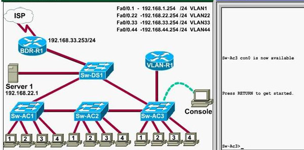
Notice: All the images in this VTP LAB are used for demonstration only, you will see slightly different images in the real CCNA exam
Question 1:
What interface did Sw-AC3 associate with source MAC address 0010.5a0c.ffba ?
a) Fa0/1
b) Fa0/3
c) Fa0/6
d) Fa0/8
e) Fa0/9
f) Fa0/12
Answer: Fa 0/8
Explanation: to find out which interface associated with a given MAC address, use the show mac-address-table command. It shows the learned MAC addresses and their associated interfaces. After entering this command, you will see a MAC address table like this:
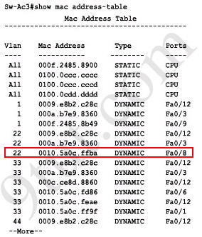
From this table we can figure out that the MAC address 0010.5a0c.ffba is associated with interface Fa0/8
Question 2:
What ports on Sw-AC3 are operating has trunks (choose two)?
a) Fa0/1
b) Fa0/3
c) Fa0/4
d) Fa0/6
e) Fa0/9
f) Fa0/12
Answer: Fa0/9 and Fa0/12
Explanation: Use the show interface trunk command to determine the trunking status of a link and VLAN status. This command lists port, its mode, encapsulation and whether it is trunking. The image below shows how it works:
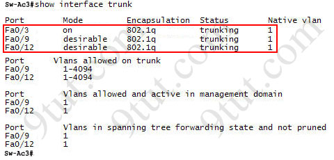
(This image is used for demonstration only)
Question 3:
What kind of router is VLAN-R1?
a) 1720
b) 1841
c) 2611
d) 2620
Answer: 2611
Explanation: VLAN-R1 is the router directly connected to Sw-Ac3 switch, so we can use the show cdp neighbors command to see:
1. Neighbor Device ID : The name of the neighbor device;
2. Local Interface : The interface to which this neighbor is heard
3. Capability: Capability of this neighboring device - R for router, S for switch, H for Host etc.
4. Platform: Which type of device the neighbor is
5. Port ID: The interface of the remote neighbor you receive CDP information
6. Holdtime: Decremental hold time in seconds
Sample output of show cdp neighbors command:
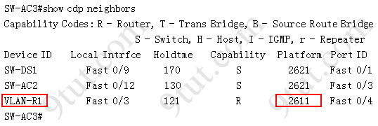
One thing I want to notice you is "Local Intrfce" in the image above refers to the local interface on the device you are running the "show cdp neighbors" command
Question 4: Which switch is the root bridge for VLAN 1?
Answer: Sw-DS1
Explanation: First we use the show spanning-tree vlan 1 to view the spanning-tree information of VLAN 1
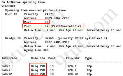
Notice that if you see all of the interface roles are Desg (designated) then you can confirm Sw-Ac3 switch is the root bridge for this VLAN (VLAN 1).
If you see there is at least one Root port in the interface roles then you can confirm Sw-Ac3 is not the root bridge because root bridge does not have root port. In this case, we notice that the root port on Sw-Ac3 switch is FastEthernet0/12, so we have to figure out which switch is associated with this port -> it is the root bridge. You can verify it with the show cdp neighbors command:
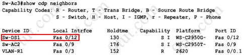
The "Local Intrfce" column refers to the interface on the switch running "show cdp neighbors" command. In this case, Sw-DS1 is associated with interface FastEthernet0/12 -> Sw-DS1 is the root bridge
Question 5: What address should be configured as the default-gateway for the host connected to interface fa 0/4 of SW-Ac3?
Answer: 192.168.44.254
Explanation:
First we have to identify which VLAN interface Fa0/4 belongs to by the show vlan command
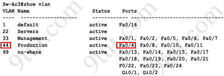
From the exhibit we know that VLAN 44 is configured on router using sub-interface Fa0/0.44 with IP address 192.168.44.254/24
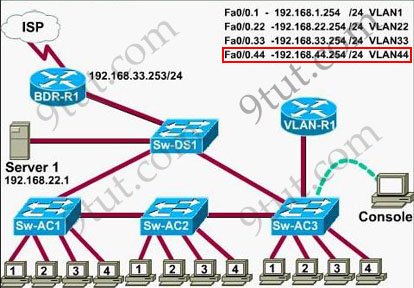
Therefore the default gateway of the host should be 192.168.44.254
Question 6: From which switch did Sw-Ac3 receive VLAN information ?
Answer: Sw-AC2
Explanation: to view the VTP configuration information, use the show vtp status command
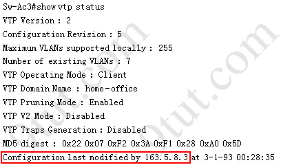
So we knew Sw-Ac3 received VLAN information from 163.5.8.3 (notice:the IP address may be different). Finally we use the show cdp neighbors detail to find out who 163.5.8.3 is:
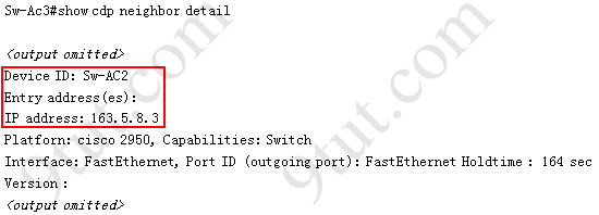
There are still some questions for the VTP SIM, I will update them soon!
Samba tutorial - Part 11
Using Samba Across Routed Networks
Andrew Tridgell states that SMB host browsing across routers is problematic. Here are his suggestions to allow this:
-------------------------------------------------------------- For cross-subnet (ie. routed) browsing you should do the following. There are other methods but they are much more complex are error prone:
1) all computers that you want visible should use a single WINS server (Samba or NT can do this)
2) the master browser for each subnet must be either NT or Samba. (Win9X doesn't communicate cross-subnet browse info correctly)
3) You should use the same workgroup name on all subnets. This is not strictly necessary but it is the simplest way to guarantee success. If you can't arrange this then you must organise for a way for browse info to propogate between subnets. (It does *not* propogate via WINS). It propogates via two mechanisms: i) each browse master notices workgroup announcements from other browse masters on the same broadcast domain ii) each non-Win9X browse master contacts the global DMB for the workgroup (typically the domain controller or a Samba box marked as the domain master) and swaps full browse info periodically. --------------------------------------------------------------
Also, Rakesh Bharania points out that Cisco routers can be configured to forward SMB traffic in a way that allows browsing. His suggestion is to configure the router interface which hosts SMB clients with a command like this:
ip helper-address x.x.x.x
where x.x.x.x is the IP address of the SMB server.
==================================================================
Acknowledgements
Special thanks to Andrew Tridgell ( tridge@linuxcare.com) for starting and directing the Samba project and for keeping this document honest.
Brad Marshall ( bmarshall@plugged.net.au) and Jason Parker ( jparker@plugged.net.au) contributed time, patience, scripting and research.
Adam Neat ( adamneat@ipax.com.au) and Dan Tager ( dtager@marsala.com) contributed the bash scripts used to back up Windows machines to a Linux host.
Matthew Flint () told me about the use of the 'interfaces' option in smb.conf.
Oleg L. Machulskiy ( machulsk@shade.msu.ru), Jeff Stern ( jstern@eclectic.ss.uci.edu), Dr. Michael Langner ( langner@fiz-chemie.de and Erik Ratcliffe ( erik@caldera.com) suggested modifications to the section on Sharing A Linux Printer With Windows Machines.
Alberto Menegazzi ( flash.egon@iol.it) contributed the MagicFilter setup to enable a Linux machine to share a Windows printer.
Rakesh Bharania ( rbharani@cisco.com) contributed the suggestion for Cisco router configuration.
Rich Gregory ( rtg2t@virginia.edu) and others suggested that this document show some details about the smbfs package and its use.
Andrea Girotto ( icarus@inca.dei.unipd.it) contributed a number of valuable suggestions throughout the document.
Thanks, also, to all of the international translators that have brought this HOWTO to the non-English speaking world: Takeo Nakano ( nakano@apm.seikei.ac.jp), Klaus-Dieter Schumacher ( Klaus-Dieter.Schumacher@fernuni-hagen.de), Andrea Girotto ( icarus@inca.dei.unipd.it), Mathieu Arnold ( arn_mat@club-internet.fr), Stein Oddvar Rasmussen ( Stein@kongsberg-energi.no) Nilo Menezes ( nmenezes@n3.com.br) and many others for whom I don't have contact details.
Samba tutorial - Part 10
Backing Up Windows Machines to a Linux Host
Adam Neat ( adamneat@ipax.com.au) kindly contributed the following script to back up Windows machines to a Linux host, using the smbclient utility. Adam says that it is used to backup Windows 3.x and NT machines to a Linux based DAT SCSI Drive.
Adam is not proud of the coding style used here, but it works. As I like to say, "If it works and its stupid, then it is not stupid".
Another Windows backup script, contributed by Dan Tager ( dtager@marsala.com), is provided below. Dan's script also backs up Unix machines via rsh, although that could be modified to use ssh rather easily.
In this script, the string 'agnea1' is the username on the Linux machine that does the backups.
#!/bin/bash

clear
echo Initialising ...
checkdate=`date | awk '{print $1}'`

if [ -f "~agnea1/backup-dir/backup-data" ]; then

       echo "ERROR: No config file for today!"
       echo "FATAL!"
       exit 1
fi

if [ -d "~agnea1/backup-dir/temp" ]; then

       echo "ERROR: No tempoary directory found!"
       echo
       echo "Attempting to create"
       cd ~agnea1
       cd backup-dir
       mkdir temp
       echo "Directory Made - temp"
fi

if [ "$1" = "" ]; then

       echo "ERROR: enter in a machine name (ie: cdwriter)"
       exit 1
fi

if [ "$2" = "" ]; then

       echo "ERROR: enter in a SMB (Lan Manager) Resource (ie: work)"
       exit 1
fi

if [ "$3" = "" ]; then

       echo "ERROR: enter in an IP address for $1 (ie:
       130.xxx.xxx.52)" exit 1
fi


#############################################################################
# Main Section
#
#############################################################################

cd ~agnea1/backup-dir/temp
rm -r ~agnea1/backup-dir/temp/*
cd ~agnea1/backup-dir/

case "$checkdate"
in
       Mon)
               echo "Backuping for Monday"
               cat backup-data | /usr/local/samba/bin/smbclient
               \\\\$1\\$2 -I$3 -N echo "Complete"

                       if [ -d "~agnea1/backup-dir/Monday" ]; then
                               echo "Directory Monday Not found ...
                               making" mkdir
                               ~agnea1/backup-dir/Monday
                       fi

               echo "Archiving ..."
               cd ~agnea1/backup-dir/temp
               tar -cf monday.tar *                echo "done ..."
               rm ~agnea1/backup-dir/Monday/monday.tar
               mv monday.tar ~agnea1/backup-dir/Monday
               ;;


       Tue)
               echo "Backuping for Tuesday"
               cat backup-data | /usr/local/samba/bin/smbclient
               \\\\$1\\$2 -I$3 -N echo "Complete"

                       if [ -d "~agnea1/backup-dir/Tuesday" ]; then
                               echo "Directory Tuesday Not found ...
                               making" mkdir
                               ~agnea1/backup-dir/Tuesday
                       fi
               echo "Archiving ..."
               cd ~agnea1/backup-dir/temp
               tar -cf tuesday.tar *
               echo "done ..."
               rm ~agnea1/backup-dir/Tuesday/tuesday.tar
               mv tuesday.tar ~agnea1/backup-dir/Tuesday
               ;;

       Wed)
               echo "Backuping for Wednesday"
               cat backup-data | /usr/local/samba/bin/smbclient
               \\\\$1\\$2 -I$3 -N echo "Complete"

                       if [ -d "~agnea1/backup-dir/Wednesday" ]; then
                               echo "Directory Wednesday Not found
                               ... making" mkdir
                               ~agnea1/backup-dir/Wednesday
                       fi
               echo "Archiving ..."
               cd ~agnea1/backup-dir/temp
               tar -cf wednesday.tar *
               echo "done ..."
            rm ~agnea1/backup-dir/Wednesday/wednesday.tar
               mv wednesday.tar ~agnea1/backup-dir/Wednesday
               ;;

       Thu)
               echo "Backuping for Thrusday"
               cat backup-data | /usr/local/samba/bin/smbclient
               \\\\$1\\$2 -I$3 -N echo "Complete"

                       if [ -d "~agnea1/backup-dir/Thursday" ]; then
                               echo "Directory Thrusday Not found ...
                               making" mkdir
                               ~agnea1/backup-dir/Thursday
                       fi
               echo "Archiving ..."
               cd ~agnea1/backup-dir/temp
               tar -cf thursday.tar *
               echo "done ..."
               rm ~agnea1/backup-dir/Thursday/thursday.tar
               mv thursday.tar ~agnea1/backup-dir/Thursday
               ;;


       Fri)
               echo "Backuping for Friday"
               cat backup-data | /usr/local/samba/bin/smbclient
               \\\\$1\\$2 -I$3 -N echo "Complete"

                       if [ -d "~agnea1/backup-dir/Friday" ]; then
                               echo "Directory Friday Not found ...
                               making" mkdir
                               ~agnea1/backup-dir/Friday
                       fi
               echo "Archiving ..."
               cd ~agnea1/backup-dir/temp
               tar -cf friday.tar *
               echo "done ..."
               rm ~agnea1/backup-dir/Friday/friday.tar
               mv friday.tar ~agnea1/backup-dir/Friday
               ;;

       *)
               echo "FATAL ERROR: Unknown variable passed for day"
               exit 1;;

esac
###########
Here's Dan's backup script:
#!/bin/bash

BACKDIR=3D/backup
WINCMD=3D/usr/bin/smbclient

function CopyWinHost(){

# tars and gzips "windows shares" to a local directory using samba's
# smbclient
# argument 1 is the remote host window's host name
# argument 2 is the share name to be backed up

  echo $1,$2,$3
  REMOTE=3D$1
  SHARE=3D$2
  DEST=3D$3

# create a tarred gzip file using samba to copy direct from a
# windows pc
# 12345 is a password.  Needs some password even if not defined on
# remote system
  $WINCMD \\\\$REMOTE\\$SHARE 12345 -Tc -|gzip > $DEST
  echo `date`": Done backing up "$REMOTE" to "$DEST
  echo
}

function CopyUnixHost(){

# tars and gzips a directory using rsh
# argument 1 is the name of the remote source host
# argument 2 is the full path to the remote source directory
# argument 3 is the name of the local tar-gzip file.  day of week
#  plus .tgz will be appended to argument 3

  REMOTE=3D$1
  SRC=3D$2
  DEST=3D$3


  if rsh $REMOTE tar -cf - $SRC |gzip > $DEST; then
     echo `date`": Done backing up "$REMOTE":"$SRC" to "$DEST
  else
    echo `date`": Error backing up "$REMOTE":"$SRC" to "$DEST
  fi

}

# $1: win=3Dbackup windows machine, unix=3Dbackup unix machine
case $1 in
  win)
     # $2=3D remote windows name, $3=3Dremote share name,
     # $4=3Dlocal destination directory
     CopyWinHost $2 $3 $4;;
  unix)
     # $2 =3D remote host, $3 =3D remote directory,
     # $4 =3D destination name
     CopyUnixHost $2 $3 $4;;
esac
Subscribe to:
Posts (Atom)


