Some basic knowledge of LANs, different topologies, and working of Local Area Networks is required to proceed further.
What is a VLAN?
To refresh your memory, a Local Area Network (LAN) is a set of connected devices like computers, hubs, and switches sharing the same pool of logical address space. Normally, a router is required to route packets from one LAN to another LAN. Traditionally, all packets within a LAN are broadcast to all other devices connected to that particular LAN.
As a result, a traditional LAN has several disadvantages as below:
* Usable bandwidth is shared among all the devices connected to the LAN
* ALL devices connected within a LAN can hear ALL the packets irrespective of whether the packet is meant for that device or not. It is possible for some unscrupulous node listening to data packets not meant for that.
* Suppose, your organization has different departments. Using a traditional LAN, when any changes take place within the organization, physical cables and devices need to be moved to reorganize the LAN infrastructure.
* A LAN cannot extend beyond its physical boundary across a WAN as in VLANs.
If you are looking for a simple networked solution for a small office, it may be a good idea to have a traditional LAN setup with a few hubs or switches. However, if you are planning for a large building or campus wide LAN for several individual departments, a VLAN is almost essential.
Virtual LANs (VLANs) can be considered as an intelligent LAN consisting of different physical LAN segments enabling them to communicate with each other as if they were all on the same physical LAN segment.
Benefits of VLAN: Several of the disadvantages of traditional LANs can be eliminated with the implementation of VLANs.
1. Improved Performance: In a traditional LAN, all the hosts within the LAN receive broadcasts, and contend for available bandwidth. As a result, the bandwidth is shared among all the connected devices within the LAN segment. If you are running high-bandwidth consumption applications such as groupware or server forms, a threshold point may easily be reached. After a threshold, the users may find the LAN too slow or un-responsive. With the use of VLAN, you can divide the big LAN into several smaller VLANs. For example, if there are two file servers, each operating at 100Mbps, in a traditional LAN both the servers have to share the LAN bandwidth of 100Mbps. If you put both the servers in separate VLANs, then both have an available bandwidth of 100Mbps each. Here the available bandwidth has been doubled.
2. Functional separation of an institute or a company: It is often required to separate the functional groups within a company or institute. For example, it might be necessary to separate HR department LAN from that of Production LAN. Traditionally, it requires a router to separate two physical LANs. However, you can set up two VLANs, one for Finance, and the other for Production without a router. A switch can route frames from one VLAN to another VLAN. With VLAN's it is easier to place a workgroup together eventhough they are physically in different buildings. In this case Finance VLAN does not forward packets to Production VLAN, providing additional security.
3. Ease of Network Maintenance:
Network maintenance include addition, removal, and changing the network users. With traditional LANs, when ever a User moves, it may be necessary to re-configure the user work station, router, and the servers. Some times, it may also be necessary to lay the cable, or reconfigure hubs and switches. If you are using VLANs, many of these reconfiguration tasks become unnecessary. For example, you can avoid network address configuration on the work station and the corresponding router if you use VLAN. This is because, routing traffic within VLANs doesn't require a router.
However, VLAN's add some administrative complexity, since the administration needs to manage virtual workgroups using VLANs.
4. Reduced Cost
VLANs minimize the network administration by way of reduced maintenance on account of workstation addition/deletion/changes. This in turn reduce the costs associated with LAN maintenance.
5. Security
Using a LAN, all work stations within the LAN get the frames meant for all other work stations within the broadcast domain. Since a VLAN splits the broadcast domain into two or more, it is possible to put work stations sharing sensitive data in one VLAN, and other work station in another VLAN. Of course, if two VLANs are not sufficient, you can split the work stations into as many VLANs as required. VLAN's can also be used to set up firewalls, restrict access, and send any intrusion alerts to the administrator.
Showing posts with label CCNA. Show all posts
Showing posts with label CCNA. Show all posts
Thursday, October 16, 2008

Wednesday, October 15, 2008
CCNA 3 Ch 1 Lab Intro using Packet Tracer 5.0
Packet Tracer 5.0
Packet Tracer 5.0 is the latest version of Cisco Networking Academy’s comprehensive networking technology teaching and learning software. Innovative features of Packet Tracer 5.0, including powerful simulation, visualization, authoring, assessment, and collaboration capabilities, will help students and teachers collaborate, solve problems, and learn concepts in an engaging and dynamic social environment.
Packet Tracer makes both teaching and learning easier - instructors and students can create their own virtual “network worlds” for exploration, experimentation, and explanation of networking concepts and technologies.
* Instructors can demonstrate technologies and configurations using Packet Tracer to teach complex CCNA-level networking concepts, making it extremely useful for lectures, group and individual labs, assessments, troubleshooting and modeling tasks, homework, games, and competitions.
* Students can design, configure and troubleshoot networks using Packet Tracer’s versatile simulation and visualization environment, which also provides the opportunity and flexibility for additional practice outside of the classroom environment.
Packet Tracer supplements classroom equipment and provides students complementary learning opportunities that are not physically possible to create in the classroom or lab. In addition, Packet Tracer supplements the CCNA curricula and Packet Tracer activities are integrated throughout both CCNA Discovery and CCNA Exploration to provide rich networking technology learning experiences.
Packet Tracer 5.0 offers a unique combination of realistic simulation and visualization experiences, complex assessment and activity authoring capabilities, and opportunities for multiuser collaboration and competition, and is available free of charge to all Networking Academy instructors, students, and alumni. Visit the Packet Tracer 5.0 resource page on Academy Connection today to download this free software and explore the new possibilities in networking education.
Saturday, October 11, 2008
ESwitching Chapter 6 - CCNA Exploration: LAN Switching and Wireless (Version 4.0) - Question and Answer
ESwitching Chapter 6 - CCNA Exploration: LAN Switching and Wireless (Version 4.0)
With answer
With answer
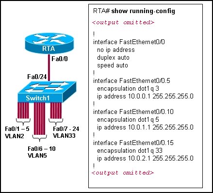
Refer to the exhibit. Switch1 is correctly configured for the VLANs that are displayed in the graphic. The configuration that is shown was applied to RTA to allow for interVLAN connectivity between hosts attached to Switch1. After testing the network, the administrator logged the following report:
Hosts within each VLAN can communicate with each other.
Hosts in VLAN5 and VLAN33 are able to communicate with each other.
Hosts connected to Fa0/1 through Fa0/5 do not have connectivity to host in other VLANs.
Why are hosts connected to Fa0/1 through Fa0/5 unable to communicate with hosts in different VLANs?
The router interface is shut down.
The VLAN IDs do not match the subinterface numbers.
All of the subinterface addresses on the router are in the same subnet.
The router was not configured to forward traffic for VLAN2.
The physical interface, FastEthernet0/0, was not configured with an IP address.
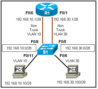
Refer to the exhibit. R1 is routing between networks 192.168.10.0/28 and 192.168.30.0/28. PC1 can ping R1 interface F0/1, but cannot ping PC3. What is causing this failure?
PC1 and PC3 are not in the same VLAN.
The PC3 network address configuration is incorrect.
The S1 interface F0/11 should be assigned to VLAN30.
The F0/0 and F0/1 interfaces on R1 must be configured as trunks.
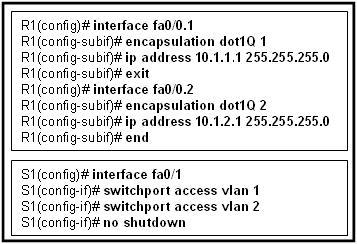
Refer to the exhibit. Port Fa0/0 on router R1 is connected to port Fa0/1 on switch S1. After the commands shown are entered on both devices, the network administrator determines that the devices on VLAN 2 are unable to ping the devices on VLAN 1. What is the likely problem?
R1 is configured for router-on-a-stick, but S1 is not configured for trunking.
R1 does not have the VLANs entered in the VLAN database.
Spanning Tree Protocol is blocking port Fa0/0 on R1.
The subinterfaces on R1 have not been brought up with the no shutdown command yet.
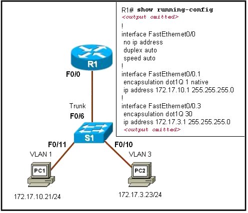
Refer to the exhibit. PC1 has attempted to ping PC2 but has been unsuccessful. What could account for this failure?
PC1 and R1 interface F0/0.1 are on different subnets.
The encapsulation is missing on the R1 interface F0/0.
An IP address has not been assigned to the R1 physical interface.
The encapsulation command on the R1 F0/0.3 interface is incorrect.
5. A router has two FastEthernet interfaces and needs to connect to four VLANs in the local network. How can this be accomplished using the fewest number of physical interfaces without unnecessarily decreasing network performance?
Implement a router-on-a-stick configuration.
Add a second router to handle the inter-VLAN traffic.
Use a hub to connect the four VLANS with a FastEthernet interface on the router.
Interconnect the VLANs via the two additional FastEthernet interfaces.

Refer to the exhibit. Which three statements describe the network design shown in the exhibit? (Choose three.)
This design will not scale easily.
The router merges the VLANs into a single broadcast domain.
This design uses more switch and router ports than are necessary.
This design exceeds the maximum number of VLANs that can be attached to a switch.
This design requires the use of the ISL or 802.1q protocol on the links between the switch and the router.
If the physical interfaces between the switch and router are operational, the devices on the different VLANs can communicate through the router.
7. In which situation could individual router physical interfaces be used for InterVLAN routing, instead of a router-on-a-stick configuration?
a network with more than 100 subnetworks
a network with a limited number of VLANs
a network with experienced support personnel
a network using a router with one LAN interface
8. What distinguishes traditional routing from router-on-a-stick?
Traditional routing is only able to use a single switch interface. Router-on-a-stick can use multiple switch interfaces.
Traditional routing requires a routing protocol. Router-on-a-stick only needs to route directly connected networks.
Traditional routing uses one port per logical network. Router-on-a-stick uses subinterfaces to connect multiple logical networks to a single router port.
Traditional routing uses multiple paths to the router and therefore requires STP. Router-on-a-stick does not provide multiple connections and therefore eliminates the need for STP.
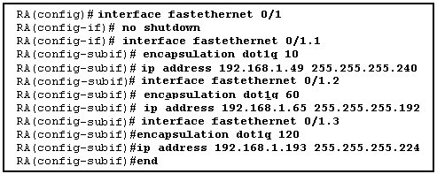
Refer to the exhibit. The commands for a router to connect to a trunked uplink are shown in the exhibit. A packet is received from IP address 192.168.1.54. The packet destination address is 192.168.1.120. What will the router do with this packet?
The router will forward the packet out interface FastEthernet 0/1.1 tagged for VLAN 10.
The router will forward the packet out interface FastEthernet 0/1.2 tagged for VLAN 60.
The router will forward the packet out interface FastEthernet 0/1.3 tagged for VLAN 120.
The router will not process the packet since the source and destination are on the same subnet.
The router will drop the packet since no network that includes the source address is attached to the router.
10. Which three elements must be used when configuring a router interface for VLAN trunking? (Choose three.)
one subinterface per VLAN
one physical interface for each subinterface
one IP network or subnetwork for each subinterface
one trunked link per VLAN
a management domain for each subinterface
a compatible trunking protocol encapsulation for each subinterface
11. What are the steps which must be completed in order to enable inter-VLAN routing using router-on-a-stick?
Configure the physical interfaces on the router and enable a routing protocol.
Create the VLANs on the router and define the port membership assignments on the switch.
Create the VLANs on the switch to include port membership assignment and enable a routing protocol on the router.
Create the VLANs on the switch to include port membership assignment and configure subinterfaces on the router matching the VLANs.
12. What two statements are true regarding the use of subinterfaces for inter-VLAN routing? (Choose two.)
subinterfaces have no contention for bandwidth
more switch ports required than in traditional inter-VLAN routing
fewer router ports required than in traditional inter-VLAN routing
simpler Layer 3 troubleshooting than with traditional inter-VLAN routing
less complex physical connection than in traditional inter-VLAN routing

Refer to the exhibit. All devices are configured as shown in the exhibit. PC2 can successfully ping the F0/0 interface on R1. PC2 cannot ping PC1. What might be the reason for this failure?
R1 interface F0/1 has not been configured for subinterface operation.
S1 interface F0/6 needs to be configured for operation in VLAN10.
S1 interface F0/8 is in the wrong VLAN.
S1 port F0/6 is not in VLAN10.
14. What is important to consider while configuring the subinterfaces of a router when implementing inter-VLAN routing?
The physical interface must have an IP address configured.
The subinterface numbers must match the VLAN ID number.
The no shutdown command must be given on each subinterface.
The IP address of each subinterface must be the default gateway address for each VLAN subnet
15.
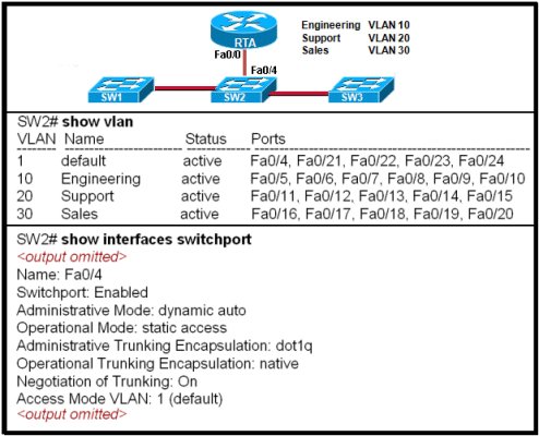
Refer to the exhibit. The network administrator correctly configures RTA to perform inter-VLAN routing. The administrator connects RTA to port 0/4 on SW2, but inter-VLAN routing does not work. What could be the possible cause of the problem with the SW2 configuration?
Port 0/4 is not active.
Port 0/4 is not a member of VLAN1.
Port 0/4 is configured in access mode.
Port 0/4 is using the wrong trunking protocol.

Refer to the exhibit. What two conclusions can be drawn from the output that is shown? (Choose two.)
The no shutdown command has not been issued on the FastEthernet 0/0 interface.
Both of the directly connected routes that are shown will share the same physical interface of the router.
A routing protocol must be configured on the network in order for the inter-VLAN routing to be successful.
Inter-VLAN routing between hosts on the 172.17.10.0/24 and 172.17.30.0/24 networks is successful on this network.
Hosts in this network must be configured with the IP address that is assigned to the router physical interface as their default gateway.
17. Devices on the network are connected to a 24-port Layer 2 switch that is configured with VLANs. Switch ports 0/2 to 0/4 are assigned to VLAN 10. Ports 0/5 to 0/8 are assigned to VLAN 20, and ports 0/9 to 0/12 are assigned to VLAN 30. All other ports are assigned to the default VLAN. Which solution allows all VLANs to communicate between each other while minimizing the number of ports necessary to connect the VLANs?
Configure ports 0/13 to 0/16 with the appropriate IP addresses to perform routing between VLANs.
Add a router to the topology and configure one FastEthernet interface on the router with multiple subinterfaces for VLANs 1, 10, 20, and 30.
Obtain a router with multiple LAN interfaces and configure each interface for a separate subnet, thereby allowing communication between VLANs.
Obtain a Layer 3 switch and configure a trunk link between the switch and router, and configure the router physical interface with an IP address on the native VLAN.
18. Which statement is true about ARP when inter-VLAN routing is being used on the network?
When router-on-a-stick inter-VLAN routing is in use, each subinterface has a separate MAC address to send in response to ARP requests.
When VLANs are in use, the switch responds to ARP requests with the MAC address of the port to which the PC is connected.
When router-on-a-stick inter-VLAN routing is in use, the router returns the MAC address of the physical interface in response to ARP requests.
When traditional inter-VLAN routing is in use, devices on all VLANs use the same physical router interface as their source of proxy ARP responses.
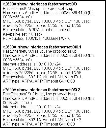
Refer to the exhibit. Which two statements are true about the operation of the subinterfaces? (Choose two.)
Incoming traffic that has a VLAN ID of 2 is processed by subinterface fa0/0.2.
Incoming traffic with VLAN ID 0 is processed by interface fa0/0.
Subinterfaces use unique MAC addresses by adding the 802.1Q VLAN ID to the hardware address.
Traffic inbound on this router is processed by different subinterfaces, depending on the VLAN from which the traffic originated.
Reliability of both subinterfaces is poor because ARP is timing out.
Both subinterfaces remain up with line protocol up, even if fa0/0 line protocol is down.
20. Which two statements are true about the interface fa0/0.10 command? (Choose two.)
The command applies VLAN 10 to router interface fa0/0.
The command is used in the configuration of router-on-a-stick inter-VLAN routing.
The command configures a subinterface.
The command configures interface fa0/0 as a trunk link.
Because the IP address is applied to the physical interface, the command does not include an IP address
Thursday, October 9, 2008
Common commands you should master when working with the Cisco IOS
The Cisco IOS provides thousands of commands, and configuring it can be challenging. Here are 10 commands you need to know, inside and out, when using the Cisco IOS.
#1: The “?”
It may seem entirely too obvious that you should know how to type ? to ask for help when using the Cisco IOS. However, the Cisco IOS is completely different from other operating systems when it comes to using the question mark (help key). As the IOS is a command-line operating system with thousands of possible commands and parameters, using the ? can save your day.
You can use the command in many ways. First, use it when you don’t know what command to type. For example, type ? at the command line for a list of all possible commands. You can also use ? when you don’t know what a command’s next parameter should be. For example, you might type show ip ? If the router requires no other parameters for the command, the router will offer CR as the only option. Finally, use ? to see all commands that start with a particular letter. For example, show c? will return a list of commands that start with the letter c.
#2: show running-configuration
The show running-config command shows the router, switch, or firewall’s current configuration. The running-configuration is the config that is in the router’s memory. You change this config when you make changes to the router. Keep in mind that config is not saved until you do a copy running-configuration startup-configuration. This command can be abbreviated sh run.
#3: copy running-configuration startup-configuration
This command will save the configuration that is currently being modified (in RAM), also known as the running-configuration, to the nonvolatile RAM (NVRAM). If the power is lost, the NVRAM will preserve this configuration. In other words, if you edit the router’s configuration, don’t use this command and reboot the router–those changes will be lost. This command can be abbreviated copy run start. The copy command can also be used to copy the running or startup configuration from the router to a TFTP server in case something happens to the router.
#4: show interface
The show interface command displays the status of the router’s interfaces. Among other things, this output provides the following:
* Interface status (up/down)
* Protocol status on the interface
* Utilization
* Errors
* MTU
This command is essential for troubleshooting a router or switch. It can also be used by specifying a certain interface, like shint fa0/0.
#5: show ip interface
Even more popular than show interface are show ip interface and show ip interface brief. The show ip interface command provides tons of useful information about the configuration and status of the IP protocol and its services, on all interfaces. The show ip interface brief command provides a quick status of the interfaces on the router, including their IP address, Layer 2 status, and Layer 3 status.
#6: config terminal, enable, interface, and router
Cisco routers have different modes where only certain things can be shown or certain things can be changed. Being able to move between these modes is critical to successfully configuring the router.
For example, when logging in, you start off at the user mode (where the prompt looks like >). From there, you type enable to move to privileged mode (where the prompt looks like #). In privileged mode, you can show anything but not make changes. Next, type config terminal (or config t) to go to global configuration mode (where the prompt looks like router(config)# ). From here, you can change global parameters. To change a parameter on an interface (like the IP address), go to interface configuration mode with the interface command (where the prompt looks like router(config-if)#). Also from the global configuration mode, you can go into router configuration using the router {protocol} command. To exit from a mode, type exit.
#7: no shutdown
The no shutdown command enables an interface (brings it up). This command must be used in interface configuration mode. It is useful for new interfaces and for troubleshooting. When you’re having trouble with an interface, you may want to try a shut and no shut. Of course, to bring the interface down, reverse the command and just say shutdown. This command can be abbreviated no shut.
#8: show ip route
The show ip route command is used to show the router’s routing table. This is the list of all networks that the router can reach, their metric (the router’s preference for them), and how to get there. This command can be abbreviated shipro and can have parameters after it, like shiproospf for all OSPF routers. To clear the routing table of all routes, you do clear ip route *. To clear it of just one route, do clear ip route 1.1.1.1 for clearing out that particular network.
#9: show version
The show version command gives you the router’s configuration register (essentially, the router’s firmware settings for booting up), the last time the router was booted, the version of the IOS, the name of the IOS file, the model of the router, and the router’s amount of RAM and Flash. This command can be abbreviated shver.
#10: debug
The debug command has many options and does not work by itself. It provides detailed debugging output on a certain application, protocol, or service. For example, debug ip route will tell you every time a router is added to or removed from the router.
Tuesday, October 7, 2008
How to learn CCNA efficiently?
Following is some comments on how to learn CCNA efficient. I think it is helpful.
1. I bought both Lammle's book, plus the Cisco PressICND1, and ICND2 books by Wendell Odom
I tend to recall commands and show output much better from hands-on than from the text. I may be wrong but it seems that way to me.
1. I bought both Lammle's book, plus the Cisco PressICND1, and ICND2 books by Wendell Odom
I like Odom's books and as there are two (smaller) ones, I can carry one and read on the train/plane. I prefer the style to Lammle's book, but I'm sure mileage varies.
You should also consider doing a CCNA course or bootcamp. I recently attende one. In the interest of fair disclosure, I work for Global Knowledge!
2. I think the best advice I can give you regarding the 640-802 is to subnet, subnet and then subnet some more. Only when you have a true grasp on the complexities of subnetting and general IP addressing schemes can you really begin to appreciate other topics.
The CISCO press books are a little dry but they are packed with the information required. I would probably then plump for a ExamCram volume as a reference point in the last few weeks before the exam. These books will not teach you the topics in any great depth but they can act as good benchmarks.
3. Lammlee's book is a good resource. I also used the Transender practice exams and purchased a couple of routers and switches off ebay to practice on. I was able to pass the ICND1 on the first attempt using only these resources. (I decided to go the two-exam route)
The ICND2 exam is a little tougher IMO. Make sure you understand spanning tree, OSPF, NAT/PAT.
4. Odom's (Cisco Press) ICND1 and ICND2 and both are excellent.
I used Odom's ICND1 to prepare for the 1st exam. I followed his study plan recommendations and did very well on the exam.
I'm using Odom's ICND2 now to prepare for next exam and my studies appear to be going well. Below is a summary of what I'm doing.
- I'm using both the ICND1 and ICND2 texts to prepare as if I'm studying for the composite (640-802) exam. I've found this helps me better understand topics covered in ICND2 text.
- After I read a topic in ICND2, I go back through the material and practice the commands and configurations on my home lab. I go over and over the 'show' commands used.
- I spend 3-4 hours a week getting more hands-on to drill in what I've covered to date.
I tend to recall commands and show output much better from hands-on than from the text. I may be wrong but it seems that way to me.
I purchased Lammle's text for the composite (640-802) exam thinking I would read it in conjunction with the Odom texts. Again, maybe it's just me, but that didn't work well for me. In fact, I pulled Lammle's text off the shelf tonight to read his section trunking, vtp, etc. I had already covered the material in Odom's text and I thought Lammle's would help me catch anything I missed. Didn't work. In fact, I stopped and put it back on the shelf because I didn't want it to confuse me. (It also appears to me that Lammle doesn't devote as much time as I need to some topics.)
5. There are a number of resources, Mirza - to some degree it depends on how you learn best.
I've posted above two sets of books (Lamie and Odom) that for me are very good. I guess these are a great starting point.
In addition to this, you might consider taking a training course. I'm biased because I work there, but take a look at Global Knowledge's classes (www.globalknowledge.com, or www.globalknowledge.net). Depending on how much you can do youself, consider the CCNA bootcamp vs the ICND1/ICND2 classes.
Getting some real hardware or a good simulator is also important. Boson's product looks pretty good, and there'a an open souce product (but that needs actual IOS images that may not be readily available to you). But picking up a couple of switches and a router should not be too expensive (ebay to the rescue).
Learn CCNA in 5 days
 Learn CCNA in 5 days | 24.85MB
The Cisco CCNA network associate certification validates the ability to install, configure, operate, and troubleshoot medium-size routed and switched networks, including implementation and verification of connections to remote sites in a WAN. This new curriculum includes basic mitigation of security threats, introduction to wireless networking concepts and terminology, and performance-based skills. This new curriculum also includes (but is not limited to) the use of these protocols: IP, Enhanced Interior Gateway Routing Protocol (EIGRP), Serial Line Interface Protocol Frame Relay, Routing Information Protocol Version 2 (RIPv2),VLANs, Ethernet, access control lists (ACLs)
Download:
Monday, October 6, 2008
Pass4Sure 640-802 v3.20
 Exam Number/Code: 640-802
Exam Name: Cisco Certified network Associate
“Cisco Certified Network Associate”, also known as 640-802 exam, is a Cisco certification.
Preparing for the 640-802 exam? Searching 640-802 Test Questions, 640-802 Practice Exam, 640-802 Dumps?
With the complete collection of questions and answers, Pass4sure has assembled to take you through 254 Q&As to your 640-802 Exam preparation. In the 640-802 exam resources, you will cover every field and category in CCNA helping to ready you for your successful Cisco Certification.
Go to our forum to download lastest version of Pass4Sure
http://www.youthgeneration.net/forum/index.php?topic=59.0
Note: This program run in Java JDK 1.6. You should upgrade your java to latest version JDK1.6
Tuesday, September 23, 2008
CCNA-V4-S4-Final
Result = 94%
1. A technician has been asked to run Cisco SDM one-step lockdown on the router of a customer. What will be the result of this process?
1. A technician has been asked to run Cisco SDM one-step lockdown on the router of a customer. What will be the result of this process?
Traffic is only forwarded from SDM-trusted Cisco routers.
Security testing is performed and the results are saved as a text file stored in NVRAM.
The router is tested for potential security problems and any necessary changes are made.
All traffic entering the router is quarantined and checked for viruses before being forwarded.
2. Refer to the exhibit. A network administrator is trying to configure a router to use SDM but it is not functioning correctly. What could be the problem?
The username and password are not configured correctly.
The authentication method is not configured correctly.
The HTTP timeout policy is not configured correctly.
The vtys are not configured correctly.
3. Refer to the exhibit. How is the TCP/IP configuration information specified by the default-router and dns-server commands made available?
The TCP/IP information is forwarded to a 10.0.1.3 to be supplied to DHCP clients.
The TCP/IP information is used by DHCP clients that are configured to request a configuration from R1.
The TCP/IP information is supplied to any DHCP client on the network connected to the FastEthernet 0/0 interface of R1.
The TCP/IP information is applied to each packet that enters R1 through the FastEthernet 0/0 interface that are hosts on the 10.0.1.0 /24 network except packets from addresses 10.0.1.2, 10.0.1.16, and 10.0.1.254.
4. What is a major characteristic of a worm?
malicious software that copies itself into other executable programs
tricks users into running the infected software
a set of computer instructions that lies dormant until triggered by a specific event
exploits vulnerabilities with the intent of propagating itself across a network
5. Refer to the exhibit. What can be concluded from the exhibited output of the debug ip nat command?
The 10.1.1.225 host is exchanging packets with the 192.168.0.10 host.
The native 10.1.200.254 address is being translated to 192.168.0.10.
The 192.168.0.0/24 network is the inside network.
Port address translation is in effect.
6. A technician is talking to a colleague at a rival company and comparing DSL transfer rates between the two companies. Both companies are in the same city, use the same service provider, and have the same rate/service plan. What is the explanation for why Company A reports higher download speeds than Company B?
Company B has a higher volume of POTS voice traffic than Company A.
Company B shares the conection to the DSLAM with more clients than Company A.
Company A only uses microfilters on branch locations.
Company A is closer to the service provider.
7. Refer to the exhibit. Which statement correctly describes how Router1 processes an FTP request entering interface s0/0/0, destined for an FTP server at IP address 192.168.1.5?
It matches the incoming packet to the access-list 201 permit any any statement and allows the packet into the router.
It reaches the end of ACL 101 without matching a condition and drops the packet because there is no access-list 101 permit any any statement.
It matches the incoming packet to the access-list 101 permit ip any 192.168.1.0 0.0.0.255 statement, ignores the remaining statements in ACL 101, and allows the packet into the router.
It matches the incoming packet to the access-list 201 deny icmp 192.168.1.0 0.0.0.255 any statement, continues comparing the packet to the remaining statements in ACL 201 to ensure that no subsequent statements allow FTP, and then drops the packet.
8. Refer to the exhibit. Which two conclusions can be drawn from the output shown? (Choose two.)
This network is experiencing congestion.
The Frame Relay connection is in the process of negotiation.
Data is not flowing in this network.
The network is discarding eligible packets.
The DLCI is globally significant.
9. A system administrator must provide Internet connectivity for ten hosts in a small remote office. The ISP has assigned two public IP addresses to this remote office. How can the system administrator configure the router to provide Internet access to all ten users at the same time?
Configure DHCP and static NAT.
Configure dynamic NAT for ten users.
Configure static NAT for all ten users.
Configure dynamic NAT with overload.
10. Refer to the exhibit. Company ABC expanded its business and recently opened a new branch office in another country. IPv6 addresses have been used for the company network. The data servers Server1 and Server2 run applications which require end-to-end functionality, with unmodified packets that are forwarded from the source to the destination. The edge routers R1 and R2 support dual stack configuration. What solution should be deployed at the edge of the company network in order to successfully interconnect both offices?
a new WAN service supporting only IPv6
NAT overload to map inside IPv6 addresses to outside IPv4 address
a manually configured IPv6 tunnel between the edge routers R1 and R2
static NAT to map inside IPv6 addresses of the servers to an outside IPv4 address and dynamic NAT for the rest of the inside IPv6 addresses
11. Refer to the exhibit. You are a network administrator who has been tasked with completing the Frame Relay topology that interconnects two remote sites. How should the point-to-point subinterfaces be configured on HQ to complete the topology?
HQ(config-subif)#frame-relay interface-dlci 103 on Serial 0/0/0.1
HQ(config-subif)#frame-relay interface-dlci 203 on Serial 0/0/0.2
HQ(config-subif)#frame-relay interface-dlci 301 on Serial 0/0/0.1
HQ(config-subif)# frame-relay interface-dlci 302 on Serial 0/0/0.2
HQ(config-subif)#frame-relay map ip 172.16.1.1 103 broadcast on Serial 0/0/0.1
HQ(config-subif)#frame-relay map ip 172.16.2.2 203 broadcast on Serial 0/0/0.2
HQ(config-subif)#frame-relay map ip 172.16.1.1 301 broadcast on Serial 0/0/0.1
HQ(config-subif)#frame-relay map ip 172.16.2.2 302 broadcast on Serial 0/0/0.2
12. An established company has recently transitioned from outsourced LAN support to a completely in-house staff. The outsourcing company is no longer in business, so no records are available. There are many user complaints about application speed and availability. What two considerations apply to this situation? (Choose two.)
A network utilization baseline should quickly reveal application availability.
A period of 24 to 48 hours should provide a sufficient baseline to track normal network activity.
It is easier to start with monitoring all available data inputs on application servers, and then fine-tune to fewer variables along the way.
The initial baseline results have little relevance to current values after the network has been modified or grown in usage.
When it is practical, network administrators should attempt to automate the collection of performance data and stay away from manual collection.
Creating a network baseline data helps determine device thresholds for alerting.
13. Which combination of Layer 2 protocol and authentication should be used to establish a link without sending authentication information in plain text between a Cisco and a non-Cisco router?
PPP with PAP
PPP with CHAP
HDLC with PAP
HDLC with CHAP
14. An administrator is unable to receive e-mail. While troubleshooting the problem, the administrator is able to ping the local mail server IP address successfully from a remote network and can successfully resolve the mail server name to an IP address via the use of the nslookup command. At what OSI layer is the problem most likely to be found?
physical layer
data link layer
network layer
application layer
15. When configuring a Frame Relay connection, what are two instances when a static Frame Relay map should be used? (Choose two.)
when the remote router is a non-Cisco router
when the remote router does not support Inverse ARP
when the local router is using IOS Release 11.1 or earlier
when broadcast traffic and multicast traffic over the PVC must be controlled
when globally significant rather than locally significant DLCIs are being used
16. Which three statements are true about creating and applying access lists? (Choose three.)
Access list entries should filter in the order from general to specific.
One access list per port per protocol per direction is permitted.
Standard ACLs should be applied closest to the source while extended ACLs should be applied closest to the destination.
There is an implicit deny at the end of all access lists.
Statements are processed sequentially from top to bottom until a match is found.
The inbound keyword refers to traffic entering the network from the router interface where the ACL is applied.
17. Which technology would provide the highest bandwidth connections between company sites at the lowest cost?
broadband Internet site-to-site VPN connections
satellite based network connections
dedicated point-to-point circuits
Frame Relay PVCs
18. Refer to the exhibit. This serial interface is not functioning correctly. Based on the output shown, what is the most likely cause?
improper LMI type
interface reset
PPP negotiation failure
unplugged cable
19. What three statements describe the roles of devices in a WAN? (Choose three.)
A CSU/DSU terminates a digital local loop.
A modem terminates a digital local loop.
A CSU/DSU terminates an analog local loop.
A modem terminates an analog local loop.
A router is commonly considered a DTE device.
A router is commonly considered a DCE device.
20. A network administrator is instructing a technician on best practices for applying ACLs. Which suggestion should the administrator provide?
Named ACLs are less efficient than numbered ACLs.
Standard ACLs should be applied closest to the core layer.
ACLs applied to outbound interfaces are the most efficient.
Extended ACLs should be applied closest to the source that is specified by the ACL.
21. Refer to the exhibit. Branch A has a Cisco router. Branch B has a non-Cisco router set for IETF encapsulation. After the commands shown are entered, R2 and R3 fail to establish the PVC. The R2 LMI is Cisco, and the R3 LMI is ANSI. The LMI is successfully established at both locations. Why is the PVC failing?
The PVC to R3 must be point-to-point.
LMI types must match on each end of a PVC.
The ietf parameter is missing from the frame-relay map ip 10.10.10.3 203 command.
The PVCs at R2 use different encapsulation types. A single port can only support one encapsulation type.
22. Which statement is true regarding wildcard masks?
The wildcard mask and subnet mask perform the same function.
The wildcard mask is always the inverse of the subnet mask.
A "0" in the wildcard mask identifies IP address bits that must be checked.
A "1" in the wildcard mask identifies a network or subnet bit.
23. Refer to the exhibit. What is placed in the address field in the header of a frame that will travel from the DC office of ABC Company to the
MAC address of the
MAC address of the DC router
192.168.1.25
192.168.1.26
DLCI 100
DLCI 200
24 .A company is looking for a WAN solution to connect its headquarters site with four remote sites. What advantage would dedicated leased lines provide to the customer compared to a shared Frame Relay solution?
lower cost
lower latency and jitter
variable bandwidth capacity
fewer physical router interfaces
25. Refer to the exhibit. RIPv2 has been configured on all routers in the network. Routers R1 and R3 do not receive RIP routing updates. On the basis of the provided configuration, what should be enabled on router R2 to remedy the problem?
proxy ARP
CDP updates
SNMP services
RIP authentication
26. What are the symptoms when the s0/0/0 interface on a router is attached to an operational CSU/DSU that is generating a clock signal, but the far end router on the point-to-point link has not been activated?
show controllers indicates cable type DCE V.35. show interfaces s0/0/0 indicates serial down, line protocol down.
show controllers indicates cable type DCE V.35. show interfaces s0/0/0 indicates serial up, line protocol down.
show controllers indicates cable type DTE V.35. show interfaces s0/0/0 indicates serial up, line protocol down.
show controllers indicates cable type DTE V.35. show interfaces s0/0/0 indicates serial down, line protocol down.
27. Which statement about a VPN is true?
VPN link establishment and maintenance is provided by LCP.
DLCI addresses are used to identify each end of the VPN tunnel.
VPNs use virtual Layer 3 connections that are routed through the Internet.
Only IP packets can be encapsulated by a VPN for tunneling through the Internet.
28. Refer to the exhibit. Partial results of the show access-lists and show ip interface FastEthernet 0/1 commands for router R3 are shown. There are no other ACLs in effect. Host A is unable to telnet to host B. Which action will correct the problem but still restrict other traffic between the two networks?
Apply the ACL in the inbound direction.
Apply the ACL on the FastEthernet 0/0 interface.
Reverse the order of the TCP protocol statements in the ACL.
Modify the second entry in the list to permit tcp host 192.168.10.10 any eq telnet .
29. Refer to the exhibit. What happens if the network administrator issues the commands shown when an ACL called Managers already exists on the router?
The commands overwrite the existing Managers ACL.
The commands are added at the end of the existing Managers ACL.
The network administrator receives an error stating that the ACL already exists.
The commands will create a duplicate Managers ACL containing only the new commands being entered.
30. Which three statements accurately describe a security policy? (Choose three.)
It creates a basis for legal action if necessary.
It defines a process for managing security violations.
It defines acceptable and unacceptable use of network resources.
The remote access policy is a component of the security policy that governs acceptable use of e-mail systems.
It is kept private from users to prevent the possibility of circumventing security measures.
It provides step-by-step procedures to harden routers and other network devices.
31. Refer to the exhibit. The link between the CTRL and BR_1 routers is configured as shown in the exhibit. Why are the routers unable to establish a PPP session?
The clock rate must be 56000.
The usernames are misconfigured.
The IP addresses are on different subnets.
The clock rate is configured on the wrong end of the link.
The CHAP passwords must be different on the two routers.
Interface serial 0/0/0 on CTRL must connect to interface serial 0/0/1 on BR_1.
32. What effect would the Router1(config-ext-nacl)# permit tcp 172.16.4.0 0.0.0.255 any eq www command have when implemented inbound on the f0/0 interface?
All TCP traffic is permitted, and all other traffic is denied.
The command is rejected by the router because it is incomplete.
All traffic from 172.16.4.0/24 is permitted anywhere on any port.
Traffic originating from 172.16.4.0/24 is permitted to all TCP port 80 destinations.
33. What can a network administrator do to recover from a lost router password?
use the copy tftp: flash: command
boot the router to bootROM mode and enter the b command to load the IOS manually
telnet from another router and issue the show running-config command to view the password
boot the router to ROM monitor mode and configure the router to ignore the startup configuration when it initializes
34. A router in a Frame Relay network needs to forward a message received from a host. What two methods does the router use to identify the correct VC to forward the message? (Choose two.)
The router forwards the frame to all ports in the network and learns the address from the reply frame.
The destination host IP address is embedded in the DLCI.
The router searches Inverse ARP tables for maps of DLCIs to IP addresses.
A table of static mappings can be searched.
The router broadcasts a request for the required IP address.
35. Refer to the exhibit. From the output of the show interface commands, at which OSI layer is a fault indicated?
application
transport
network
data link
physical
36. Refer to the exhibit. The network administrator creates a standard access control list to prohibit traffic from the 192.168.1.0/24 network from reaching the 192.168.2.0/24 network while still permitting Internet access for all networks. On which router interface and in which direction should it be applied?
interface fa0/0/0, inbound
interface fa0/0/0, outbound
interface fa0/0/1, inbound
interface fa0/0/1, outbound
37. Refer to the exhibit. The SSH connections between the remote user and the server are failing. The correct configuration of NAT has been verified. What is the most likely cause of the problem?
SSH is unable to pass through NAT.
There are incorrect access control list entries.
The access list has the incorrect port number for SSH.
The ip helper command is required on S0/0/0 to allow inbound connections.
38. Refer to the exhibit. A technician issues the show interface s0/0/0 command on R1 while troubleshooting a network problem. What two conclusions can be determined by from the output shown? (Choose two.)
The bandwidth has been set to the value of a T1 line.
Encapsulation should of this inteface be changed to PPP.
There is no failure indicated in an OSI Layer 1 or Layer 2.
The physical connection between the two routers has failed.
The IP address of S0/0 is invalid, given the subnet mask being used.
39. Refer to the exhibit. A packet is being sent from Host A to Host B through the VPN tunnel between R1 and R3. When the packet first arrives at R3, what are the source and destination IP addresses of the packet?
Source 192.168.1.2 - Destination 192.168.4.2
Source 192.168.3.1 - Destination 192.168.3.2
Source 192.168.2.1 - Destination 192.168.3.2
Source 192.168.3.1 - Destination 192.168.4.2
40. An administrator is configuring a dual stack router with IPv6 and IPv4 using RIPng. The administrator receives an error message when trying to enter the IPv4 routes into RIPng. What is the cause of the problem?
RIPng is incompatible with dual-stack technology.
All interfaces have been configured with the incorrect IPv4 addresses.
RIPv1 or RIPv2 needs to be configured in addition to RIPng to successfully use IPv4.
When IPv4 and IPv6 are configured on the same interface, all IPv4 addresses are shut down in favor of the newer technology.
41. Which wireless solution can provide mobile users with non line-of-sight broadband Internet access at speeds comparable to DSL or cable?
Wi-Fi
WiMAX
satellite
Metro Ethernet
42. A network administrator added two switches and a new VLAN over the past weekend. How can the administrator determine if the additions and changes improved performance and availability on the company intranet?
Perform a baseline test and compare the current values to values that were obtained in previous weeks.
Interview departmental secretaries and determine if they think load time for web pages is improved.
Compare the hit counts on the company web server for the current week to the values that were recorded from previous weeks.
Performance on the intranet can be determined by monitoring load times of company web pages from remote sites.
43. Refer to the exhibit. The network administrator is adding R1 to an existing network. As a part of the corporate IT procedures, the administrator attempts to back up the router Cisco IOS software of R1 and receives the output shown. The network administrator then attempts unsuccessfully to ping the TFTP server from the console session. What should be done next to isolate this problem?
From R2, validate that interface Fa0/0 is operational.
From the TFTP server, verify that the software on the TFTP server is operational.
From the TFTP server, confirm there is enough room on the TFTP server for the Cisco IOS software.
From the console session, make sure that R1 has a route to the network where the TFTP server resides.
44. What functionality do access control lists provide when implementing dynamic NAT on a Cisco router?
defines which addresses can be translated
defines which addresses are assigned to a NAT pool
defines which addresses are allowed out of the router
defines which addresses can be accessed from the inside network
45. A network administrator is working with an applications team to fix a problem that a server based application is having with response time. The administrator has examined the network portions of the data path and identified several possible problem areas. The applications team has simultaneously identified potential issues with the current release of software. The network administrator begins addressing the network issues while the applications team implements software patches.
Which statement applies to this situation?
Changes to the network will reveal problems that are caused by the new patches.
Scheduling will be more difficult if the network and software teams work independently.
It will be difficult to isolate the problem if two teams are implementing changes independently.
Results from changes will be easier to reconcile and document if each team works in isolation.
46. Refer to the exhibit. R1 is performing NAT overload for the 10.1.1.0/24 inside network. Host A has sent a packet to the web server. What is the destination IP address of the return packet from the web server?
10.1.1.2:1234
172.30.20.1:1234
172.30.20.1:3333
192.168.1.2:80
47. Which three guidelines would help contribute to creating a strong password policy? (Choose three.)
Once a good password is created, do not change it.
Deliberately misspell words when creating passwords.
Create passwords that are at least 8 characters in length.
Use combinations of upper case, lower case, and special characters.
Write passwords in locations that can be easily retrieved to avoid being locked out.
Use long words found in the dictionary to make passwords that are easy to remember.
48. What will be the result of adding the command ip dhcp excluded-address 172.16.4.1 172.16.4.5 to the configuration of a local router that has been configured as a DHCP server?
Traffic that is destined for 172.16.4.1 and 172.16.4.5 will be dropped by the router.
Traffic will not be routed from clients with addresses between 172.16.4.1 and 172.16.4.5.
The DHCP server function of the router will not issue the addresses between 172.16.4.1 and 172.16.4.5.
The router will ignore all traffic that comes from the DHCP servers with addresses 172.16.4.1 and 172.16.4.5.
49. Which two statements are true about IPv6? (Choose two.)
Security options are build into IPv6.
IPv6 addresses require less router overhead to process.
IPv6 can only be configured on an interface that does not have IPv4 on it.
There is no way to translate between IPv4 addresses and IPv6 addresses.
When enabled on a router, IPv6 can automatically configure link-local IPv6 addresses on all interfaces.
50. Refer to the exhibit. A network administrator has issued the commands that are shown on Router1 and Router2. A later review of the routing tables reveals that neither router is learning the LAN network of the neighbor router. What is most likely the problem with the RIPng configuration?
The serial interfaces are in different subnets.
The RIPng process is not enabled on interfaces.
The RIPng network command is not configured.
The RIPng processes do not match between Router1 and Router2.
51. At what physical location does the responsibilty for a WAN connection change from the user to the service provider?
demilitarized zone (DMZ)
demarcation point
local loop
cloud
52. Refer to the exhibit. A host connected to Fa0/0 is unable to acquire an IP address from this DHCP server. The output of the debug ip dhcp server command shows "DHCPD: there is no address pool for 192.168.1.1". What is the problem?
The 192.168.1.1 address has not been excluded from the DHCP pool.
The pool of addresses for the 192Network pool is incorrect.
The default router for the 192Network pool is incorrect.
The 192.168.1.1 address is already configured on Fa0/0.
53. Which three functions are provided by the Local Management Interface used in Frame Relay networks? (Choose three.)
exchange information about the status of virtual circuits
map DLCIs to network addresses
provide flow control
provide error notification
provide congestion notification
send keepalive packets to verify operation of the PVC
54. Which three items are LCP options that can be configured for PPP? (Choose three.)
CHAP
Stacker
IPCP
CDPCP
Multilink
55. What are two main components of data confidentiality? (Choose two.)
checksum
digital certificates
encapsulation
encryption
Saturday, September 13, 2008
CCNA VTP SIM Question == Updated from lastest CCNA exam on 09-10-2008
(Updated from lastest CCNA exam on 09-10-2008)
Question:
This task requires you to use the CLI of Sw-AC3 to answer five multiple-choice questions. This does not require any configuration.
To answer the multiple-choice questions, click on the numbered boxes in the right panel.
There are five multiple-choice questions with this task. Be sure to answer all five questions before leaving this item.
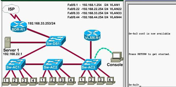
Notice: All the images in this VTP LAB are used for demonstration only, you will see slightly different images in the real CCNA exam
Question 1:
What interface did Sw-AC3 associate with source MAC address 0010.5a0c.ffba ?
a) Fa0/1
b) Fa0/3
c) Fa0/6
d) Fa0/8
e) Fa0/9
f) Fa0/12
Answer: Fa 0/8
Explanation: to find out which interface associated with a given MAC address, use the show mac-address-table command. It shows the learned MAC addresses and their associated interfaces. After entering this command, you will see a MAC address table like this:
From this table we can figure out that the MAC address 0010.5a0c.ffba is associated with interface Fa0/8
Question 2:
What ports on Sw-AC3 are operating has trunks (choose two)?
a) Fa0/1
b) Fa0/3
c) Fa0/4
d) Fa0/6
e) Fa0/9
f) Fa0/12
Answer: Fa0/9 and Fa0/12
Explanation: Use the show interface trunk command to determine the trunking status of a link and VLAN status. This command lists port, its mode, encapsulation and whether it is trunking. The image below shows how it works:
(This image is used for demonstration only)
Question 3:
What kind of router is VLAN-R1?
a) 1720
b) 1841
c) 2611
d) 2620
Answer: 2611
Explanation: VLAN-R1 is the router directly connected to Sw-Ac3 switch, so we can use the show cdp neighbors command to see:
1. Neighbor Device ID : The name of the neighbor device;
2. Local Interface : The interface to which this neighbor is heard
3. Capability: Capability of this neighboring device - R for router, S for switch, H for Host etc.
4. Platform: Which type of device the neighbor is
5. Port ID: The interface of the remote neighbor you receive CDP information
6. Holdtime: Decremental hold time in seconds
Sample output of show cdp neighbors command:
One thing I want to notice you is "Local Intrfce" in the image above refers to the local interface on the device you are running the "show cdp neighbors" command
Question 4: Which switch is the root bridge for VLAN 1?
Answer: Sw-DS1
Explanation: First we use the show spanning-tree vlan 1 to view the spanning-tree information of VLAN 1
Notice that if you see all of the interface roles are Desg (designated) then you can confirm Sw-Ac3 switch is the root bridge for this VLAN (VLAN 1).
If you see there is at least one Root port in the interface roles then you can confirm Sw-Ac3 is not the root bridge because root bridge does not have root port. In this case, we notice that the root port on Sw-Ac3 switch is FastEthernet0/12, so we have to figure out which switch is associated with this port -> it is the root bridge. You can verify it with the show cdp neighbors command:
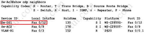
The "Local Intrfce" column refers to the interface on the switch running "show cdp neighbors" command. In this case, Sw-DS1 is associated with interface FastEthernet0/12 -> Sw-DS1 is the root bridge
Question 5: What address should be configured as the default-gateway for the host connected to interface fa 0/4 of SW-Ac3?
Answer: 192.168.44.254
Explanation:
First we have to identify which VLAN interface Fa0/4 belongs to by the show vlan command
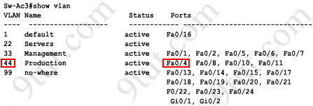
From the exhibit we know that VLAN 44 is configured on router using sub-interface Fa0/0.44 with IP address 192.168.44.254/24
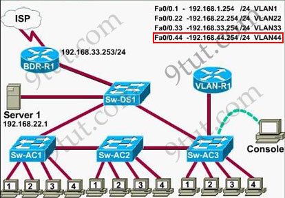
Therefore the default gateway of the host should be 192.168.44.254
Question 6: From which switch did Sw-Ac3 receive VLAN information ?
Answer: Sw-AC2
Explanation: to view the VTP configuration information, use the show vtp status command
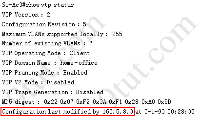
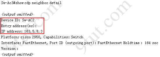
So we knew Sw-Ac3 received VLAN information from 163.5.8.3 (notice:the IP address may be different). Finally we use the show cdp neighbors detail to find out who 163.5.8.3 is:
There are still some questions for the VTP SIM, I will update them soon!
Monday, September 1, 2008
CCNA 3 with no answer 01/Sep/2008
1. Take Assessment - ESwitching Chapter 2 - CCNA Exploration: LAN Switching and Wireless (Version 4.0)
2.Take Assessment - ESwitching Chapter 5 - CCNA Exploration: LAN Switching and Wireless (Version 4.0)
3.Take Assessment - ESwitching Chapter 6 - CCNA Exploration: LAN Switching and Wireless (Version 4.0)
4.Take Assessment - ESwitching Chapter 7 - CCNA Exploration: LAN Switching and Wireless (Version 4.0)
Link download
Monday, August 25, 2008
Tips for CCIE Candidate
A. TEN TIPS FOR TAKING THE LAB EXAM
1. Read the entire exam first and check for addressing issues. Do not skip any details or sections.
2. Manage your time. Make a plan to cover all the sections in the time provided. Work out how much time you will spend on each section, keeping in mind the point value of the questions. Don’t forget to allow time at the end to verify your solutions.
3. Clarify the requirements of each question. Don’t assume requirements that aren’t mentioned in the question. During the lab, if you are in any doubt, verify your understanding of the question with the proctor.
4. Do each question as a unit. Configure and verify before moving to the next question. You may want to redraw the topology with all the details available. This will help you visualize and map the network.
5. Troubleshoot. You must know how to troubleshoot using the tools available. Although troubleshooting is important, don’t lose too much time working on a 2- or 3-point question. If you’re caught off-guard by an unfamiliar topic, don’t let it absorb too much time. Work on the things you are more comfortable with and go back to difficult items later.
6. Keep a list. During the exam, make notes on configurations and settings as you move through the exam. Make a separate list for items you have not been able to address or where you have not achieved the desired result which you’ll need to revisit.
7. Test your work. Never rely on a configuration done in the early hours of the exam. There is a possibility that an item you configured a few sections earlier can become broken and non-functional. Keep in mind that points are awarded for working configuration only.
8. Save your configurations often.
9. Don’t make any drastic changes in the last half hour of the exam.
10. Speed is vital on the exam. Review and practice core material the week before the exam to ensure you can move quickly through the less challenging questions.
B.R&S Lab Diagram
There are a lot of rumors floating around in regards to diagrams in the R&S CCIE lab. Cisco officially has said little in regards to this other than the following “the lab document has L1/L2 diagrams for the physical connectivity as well as an IP or topology diagram and an IP Routing diagram”. This is similar to what we provide in our labs but I would venture to say that they don’t take the time we do to ensure that they look as nice as ours What Cisco and we do not provide is a true layer 2 “logical” diagram but Cisco and we do provide is a physical diagram of the connections in the lab. A physical diagram is not the same as a logical layer 2 diagram. A logical layer 2 diagram will include the VLAN assignments, trunks, EtherChannels, dot1q tunnels, VTP and possibly spanning tree information like root bridges, root ports, designated ports, etc. The choice to draw out the spanning tree information will really come down to the lab itself. If there are a lot of tasks that relate to spanning tree or layer 2 traffic engineering (i.e. traffic for VLAN 100 should transit SW3, etc) then adding the spanning tree information will help answer these types of tasks.
The logical layer 3 diagram will be provided BUT the diagram they provide may not have the level of detail you want or need plus you can not write on the diagram they give you. Technically you can write on it but they will suspend you from the lab for one year . We ALWAYS recommend making your own layer 3 logical diagram. You should also draw out the diagram for every practice lab you do. Do not wait until the real lab to draw out your first diagram. As I have said before you never want to do anything in the CCIE lab for the first time other than get your number
There are two main benefits to making your own logical layer 3 diagram. First off you will find it is easier to remember what the network looks like when reading the tasks and secondly you will be able to draw and/or take notes on your own diagram. Smart people fail the lab all the time because they make stupid mistakes in the lab and by drawing out the network you will hopefully lower the chances of making these stupid mistake (i.e. configuring RIPv2 on the wrong interface, applying an ACL inbound on one interface when it should have been outbound on another, configuring a feature on the wrong router, etc). All it takes is two or three of these little mistakes and you have lost 8 or 9 points in the lab. We all know that it is hard enough to pass the lab without adding in stupid mistakes into the mix . You will also find tasks related to BGP to be easier to answer when you have a diagram that you can take notes on (i.e. who is peering with who, which exit point to use to reach another AS, etc). It is possible that when you get into the lab that basic BGP is done for you. It is normally easier to work on a network that you built from the ground up so working on a network that is 50% complete without first taking the time to discover and document what is already done will be harder.
I am sure someone will comment on this and say, “but I won’t have time to draw out the network in the real lab”. If this is the case you should not be in the lab in the first place. If it is taking you the full 8 hours to just configure the network you more than likely will not pass the lab to begin with so taking the 10 minutes to draw out the network is not going to really matter in this case. The percentage of people who pass the lab while configuring the network for the full 8 hours is slim. Most people who pass the lab complete the lab within 5.5 or 6.5 hours and have the extra time to do the diagram in the beginning.
C. CCIE course:
1. CCIE Practical Study Volume I + II
2. CCIE Routing and Switching Exam Quick Reference Sheets (Exam 350-001 v3.0)
3. CCIE Routing and Switching Flash Cards
4. CCIE Routing and Switching Practical Labs
5. Cisco BGP-4 Command and Configuration handbook
6. Cisco Catalyst QoS: Quality of Service in Campus Network
7. Cisco Frame Relay Solutions Guide
8. Cisco LAN Switching
9. Cisco OSPF Command and Configuration Handbook
10. Developing IP Multicast Network, Volume I
11. Implementing Cisco Ipv6 Network (Ipv6)
12. Inside Cisco IOS Software Architecture
13. Internet Routing Architectures, Second Edition
14. MPLS and VPN Architectures
15. MPLS and VPN Architectures Volume II
16. Routing TCP/IP Volume I, Second Edition
17. Routing TCP/IP Volume II
18. Troubleshooting IP Routing Protocols (CCIE Professional Development Series)
19. Troubleshooting Remote Access Networks (CCIE Professional Development)
20. CCIE Routing and Switching Exam Certification Guide, 3rd Edition
21. Cisco Documentation: Web site: www.cisco.com/univercd (***)
22. Configuration Ipv6 for Cisco IOS
23. Interconnections: Bridges and Routers, Second Edition
24. Internetwork Technology Overview
25. Internetwork with TCP/IP volume: Principles, Protocols, and Architecture (4th Edition)
26. Ipv6: Theory, Protocol, and Practice, 2nd Edition
27. LAN Protocol Handbook
28. Routing in the Internet (2nd Edition)
29. TCP/IP Illustrated: volume I + II + III
E. CCIE LAB R&S via InternetworkExpert
1. Bridging and Switching
- IRB và CRB: khi cần bridge và route trên cùng 1 group interface thì dùng IRB, còn chỉ cần bridge giữa 1 group interface thì dùng CRB. Điểm khác biệt quan trọng ở đây là: IRB dùng interface BVI để route còn CRB không có khái niện interface BVI nên không thể route được.
Example:
!!cấu hình IRB để bridge và route giữa 2 physical interface frame-relay s0/0/0 và s0/0/1!!
bridge irb
bridge 1 protocol ieee
bridge 1 route ip
!
interface s0/0/0
bridge-group 1
frame-relay map bridge 201 broadcast
!
interface s0/0/1
bridge-group 1
frame-relay map bridge 202 broadcast
!
interface bvi 1
ip address 192.168.1.1 255.255.255.0
!!cấu ihnhf CRB để bridge giữa 2 physical interface frame-relay s0/0/0 và s0/0/1!!
bridge crb
bridge 1 protocol ieee
!lưu ý không gõ lệnh “bridge 1 route ip” vì CRB không có “route” nếu gõ !lệnh này CRB sẽ không bridge được
!
interface s0/0/0
bridge-group 1
!
interface s0/0/1
bridge-group 1
!
end
wr
2. WAN Technologies
+ Trên Frame Relay, nếu DLCI của 1 subInterface Inactive thì subInterface đó sẽ down, thường dùng tính năng này kết hợp với frame-relay end-to-end keepalive để làm backup interface (khi DLCI inactive thì chuyển sang interface backup)
+ Trên PPP authentication giữa R4 s0/0/1 và R5 s0/0/1, muốn R4 chứng thực trước, R5 chứng thực sau ta dùng cấu hình như sau:
!!!R4
R4(config)#interface s0/0/1
R4(config-if)# encap ppp
R4(config-if)# ppp direction callout
R4(config-if)# ppp authen chap
!!!R5
R5(config)#interface s0/0/1
R5(config-if)# encap ppp
R5(config-if)# ppp direction callin
R5(config-if)# ppp authen chap
3. Interior Gateway Routing
+ Cấu hình OSPF
+ Cấu hình EIGRP
+ Khi cần chỉnh metric để loadbalance trên nhiều đường, đối với EIGRP chỉ nên chỉnh tham số delay trong công thức: metric = 256*(10.000.000/bandwidth(Kbps) + delay) (đối với k1=k3=1, k2=k4=k5=0, hay chỉ tính bandwidth và delay không tính các tham số: load, reliability và MTU)
+ Cấu hình RIP
+ Cấu hình Redistribute
+ Chú ý: khi cấu hình redistribute tương hỗ (2 chiều) thì luôn phải tuân thủ nguyên tắc: route từ routing domain A khi redistribute không được redistribute ngược trở lại vào domain A. Để làm điều này, dùng route-map như sau: (ví dụ: redistribute qua lại giữa OSPF và RIP trên router R4 và R5):
!!!R4 và R5:
route-map RIP->OSPF deny 10
match tag 110
!
route-map RIP->OSPF permit 20
set tag 120
!
route-map OSPF->RIP deny 10
match tag 120
!
route-map OSPF->RIP permit 20
set tag 110
!
router rip
redistribute ospf 1 metric 7 route-map OSPF->RIP
!
router ospf 1
redistribute rip subnets route-map RIP->OSPF
!
end
wr
+ Các phương thức để filter route (traffic engineer): distribute-list, offset-list, distance, prefix-list, route-map
+ Distribute-list, prefix-list, route-map: có thể filter hướng “in” và “out” đối với RIP và EIGRP, trong trường hợp này, router bị filter route sẽ không thể quảng bá route đó cho router láng giềng. Trong trường hợp OSPF chỉ có thể filter router hướng “in”, trong trường hợp này, distribute-list chỉ ngăn chặn không cho router install route bị filter vào routing table, tuy nhiên router này vẫn tiếp tục quảng bá LSA cho router láng giềng sau nó. Khi muốn filter phức tạp hơn, có thể kết hợp distribute-list và route-map để filter
Example:
!!filter route 192.168.0.0/24 -> 192.168.3.0/24!!
!!RIP!!
ip prefix-list PRE_FILTER deny 192.168.0.0/22 ge 24 le 24
ip prefix-list PRE_FILTER permit 0.0.0.0/0 le 32
!
router rip
distribute-list prefix PRE_FILTER in/out
!!EIGRP AS 100!!
router eigrp 100
distribute-list prefix PRE_FILTER in/out
!!OSPF!!
router ospf 1
distribute-list prefix PRE_FILTER in
!!giả sử Router A nhận được 4 subnet 192.168.0.0/24 -> 192.168.3.0/24 từ 2 Router B,C với địa chỉ IP của B,C lần lượt là: 172.16.1.1 và 172.16.2.2. Thực hiện filter trên Router A để Router A chỉ đi đến 4 subnet trên qua router B!!
!!RIP!!
ip access-list extended ACL_FILTER
deny ip host 172.16.2.2 192.168.0.0 0.0.0.255
deny ip host 172.16.2.2 192.168.1.0 0.0.0.255
deny ip host 172.16.2.2 192.168.2.0 0.0.0.255
deny ip host 172.16.2.2 192.168.3.0 0.0.0.255
permit ip any any
!
router rip
distribute-list ACL_FILTER in
!!EIGRP AS 100!!
ip prefix-list PRE_FILTER permit 192.168.0.0/22 ge 24 le 24
!
route-map RM_FILTER deny 10
match ip address prefix-list PRE_FILTER
match ip next-hop 172.16.2.2
route-map RM_FILTER permit 100
!
router eigrp 100
distribute-list route-map RM_FILTER in
!!OSPF!!
ip prefix-list PRE_FILTER permit 192.168.0.0/22 ge 24 le 24
!
route-map RM_FILTER deny 10
match ip address prefix-list PRE_FILTER
match ip next-hop 172.16.2.2
route-map RM_FILTER permit 100
!
router ospf 1
distribute-list route-map RM_FILTER in
E. IP Multicast
Example:
!! R3 candidate RP group 239.0.0.0 -> 239.255.255.255!!
ip access-list standard ACL_52
permit 239.0.0.0 0.255.255.255
ip pim send-rp-announce Loopback0 scope 16 group-list ACL_52
!! R5 candidate RP group 226.0.0.0 -> 238.255.255.255!!
ip access-list standard ACL_52
permit 226.0.0.0 1.255.255.255
permit 228.0.0.0 3.255.255.255
permit 232.0.0.0 3.255.255.255
permit 236.0.0.0 1.255.255.255
permit 238.0.0.0 0.255.255.255
!!Mapping-Agent or BootStrap Router!!
ip pim send-rp-discovery Loopback0 scope 16
ip pim rp-announce-filter rp-list ACL_R3 group-list ACL_GROUP_R3
ip pim rp-announce-filter rp-list ACL_R5 group-list ACL_GROUP_R5
!
ip access-list standard ACL_GROUP_R3
permit 239.0.0.0 0.255.255.255
!
ip access-list standard ACL_GROUP_R5
deny 224.0.0.0 1.255.255.255
deny 239.0.0.0 0.255.255.255
permit 224.0.0.0 15.255.255.255
!
ip access-list standard ACL_R3
permit 150.1.3.3
!
ip access-list standard ACL_R5
permit 150.1.5.5
Backup and Restore Cisco IOS
The copy command isn’t limited to simply backing up or restoring configuration files. It can also be used to copy your current IOS image to a TFTP server, or to apply a new IOS image to your router. Recall that the Cisco IOS image is stored in Flash memory. Before deciding to install a new IOS image, be sure that your router has enough Flash memory to support the image. Images from different feature sets may require more Flash memory than you currently have installed.
To back up the current IOS to a TFTP server, use the copy flash tftp command.
cisco2501#copy flash tftp
Source filename []? d1205.bin
Address or name of remote host []? 192.168.1.21
Destination filename [d1205.bin]?
!!!!!!!!!!!!!!!!!!!!!!!!!!!!!!!!!!!!!!!!!!!!!!!!!!!!!!!!!!!!!!!!!!!!!!!!!!!!!!!!
3289170 bytes copied in 47.668 secs (69982 bytes/sec)
While the copy operation to the TFTP server is completing, the exclamation points shown will scroll across the screen – I have eliminated many of these in order to save space. You will notice that the command requires us to provide information on the image filename and the IP address of the TFTP server. If you’re not sure of the name of the image stored in Flash, use the show flash command.
Router#show flash
System flash directory:
File Length Name/status
1 3289170 d1206.bin
[3289236 bytes used, 905068 available, 4194304 total]
4096K bytes of processor board System flash (Read/Write)
Since this router has only 4 MB of Flash, we are obviously limited to an image that will fit within that space. The contents of Flash can also be viewed using the dir command. You will always need to know the name of the images you want to back up or restore. You should also ensure that the TFTP server is available and has enough room to store the image prior to attempting a backup.
Copying a new IOS image from a TFTP server to Flash involves issuing the command copy tftp flash.
cisco2501#copy tftp flash
Address or name of remote host []? 192.168.1.21
Source filename []? d1206.bin
Destination filename [d1206.bin]?
Accessing tftp://192.168.1.21/d1206.bin...
Erase flash: before copying? [confirm]
Erasing the flash filesystem will remove all files! Continue? [confirm]
Erasing device... eeeeeeeeeeeeeeee ...erased
Erase of flash: complete
Loading d1206.bin from 192.168.1.21 (via Ethernet0): !!!!!!!!!!!!!!!!!!
!!!!!!!!!!!!!!!!!!!!!!!!!!!!!!!!!!!!!!!!!!!!!!!!!!!!!!!!!!!!!!!!!!!!!!!
[OK - 3289170/6578176 bytes]
Verifying checksum... OK (0xB6BD)
3289170 bytes copied in 89.272 secs (36956 bytes/sec)
Notice that Flash memory was erased completely before the new image was copied over to it. Otherwise, there would not have been enough space to complete the copy process. You’ll also need to issue the reload command after updating the IOS. Finally, use the show version command to ensure that the router is now running the IOS version that you intended to install. Show version also provides a quick and easy way to learn more about your router’s hardware, software, and memory.
Cisco2501#show version
Cisco Internetwork Operating System Software
IOS (tm) 2500 Software (C2500-D-L), Version 12.0(5), RELEASE SOFTWARE (fc1)
Copyright (c) 1986-1999 by cisco Systems, Inc.
Compiled Tue 15-Jun-99 20:08 by phanguye
Image text-base: 0x0000144C, data-base: 0x00637308
ROM: System Bootstrap, Version 5.2(8a), RELEASE SOFTWARE
BOOTFLASH: 3000 Bootstrap Software (IGS-RXBOOT), Version 10.2(8a), RELEASE SOFTWARE (fc1)
Router uptime is 2 days, 8 hours, 9 minutes
System restarted by reload
System image file is "flash:d1206.bin"
cisco 2500 (68030) processor (revision A) with 16384K/2048K bytes of memory.
Processor board ID 02285256, with hardware revision 00000000
Bridging software.
X.25 software, Version 3.0.0.
1 Ethernet/IEEE 802.3 interface(s)
2 Serial network interface(s)
32K bytes of non-volatile configuration memory.
4096K bytes of processor board System flash (Read/Write)
Configuration register is 0×2102
On some routers, including those in the Cisco 2500 series, IOS upgrades should be done from the limited IOS version stored in ROM. Depending upon your model and IOS version, you may be prompted to boot into the ROM-based image after issuing the copy tftp flash command, or you may need to change what are known as configuration register settings.
Subscribe to:
Posts (Atom)


