Saturday, November 15, 2008

CCNA Router Simulator Question - VTP SIM

VTP SIM TESTLET IS ANOTHER SIM EXAM QUESTION

VTP SIM

Question:
This task requires you to use the CLI of Sw-AC3 to answer five multiple-choice questions. This does not require any configuration.
To answer the multiple-choice questions, click on the numbered boxes in the right panel.
There are five multiple-choice questions with this task. Be sure to answer all five questions before leaving this item.


Important: The VTP simlet has a pool of 10 question . Test may have only 5 Questions for VTP SIM

some very usefull commands to answer this simlet:

show cdp neighbor , show cdp neighbor detail , show interface trunk or switchport , show mac-address-table, show spanning-tree, show vlan , show vtp status , show run .

The pool of 10 questions are discussed here starting with the 4 questions in the above picture.

Question 1 :

What interface did Sw-AC3 associate with source MAC address 0010.5a0c.ffba ?

Answer:

Fa 0/8 (As per the picture above)

To find out the associate interface number for a given mac address on the switch use the show mac-address-table command and search for the mac address 0010.5a0c.ffba and its associated interface number.
Question 2 :

what ports on Sw-AC3 are operating has trunks (choose two)?

Answer:

Fa 0/9 and Fa 0/12 (As per the picture above)

To find out the ports operating has trunks on a switch

Use the show interface trunk command this will display all the trunk ports configured on switch.

(or)

Use the show interface switchport command and check the output of the command for operational mode : type trunk for each and every interface.

Question 3:

What kind of router is VLAN-R1 ?

Answer:

2611 ( as per picture above)

To know details of directly connected Neighbor, use the following command on the switch show cdp neighbors command, this output gives the following details about its neighbors

Device ID, Local Interface ,Holdtme, Capability, Platform, Port ID

To know what kind of router is VLAN-R1 we need to identify its platform details from above command output.

Question 4:

Which switch is the root bridge for VLAN 1 ?

Answer:

Sw-AC3 (As per the question above in picture)

Step1: Use the Show spanning-tree vlan 1 command this output provide the mac address of the root bridge.

Step2: now use the show mac-address-table command this output associates the mac address to a interface number.

Step3: use the command show cdp neighbors this output will give us the local interface associated with the hostname(Device ID).

Question 5 :

Out of which port on switch Sw-Ac3 would a frame containing an IP packet with destination address that is not on a local LAN be forwarded?

Answer:

To forward any packet with destination address other then the subnet network of the switch, the switch usually forwards this IP packets to the layer 3 device example router connected to it.

Step1: Find the default-gateway(Router or layer 3 device) configured on the switch.

use the Show run command to view the IP address used to configure default-gateway on the switch.

Step2: Look for the router VLAN-R1 after using the show cdp neighbor detail command

Sample output of show cdp neighbor detail command for better understanding the output details

Device ID: C2950-1
Entry address(es):
Platform: Cisco WS-C2950T-24, Capabilities: Switch IGMP
Interface: FastEthernet0/0, Port ID (outgoing port): FastEthernet0/15
Holdtime : 139 sec

Two things to notice from above output

Interface: FastEthernet0/0 this statement provides that the neighbor(c2950-1) is connected to fa 0/0 on the c3660-2 local switch.

Port ID (outgoing port): FastEthernet0/15 this explains that neighbor (c2950-1) uses fa 0/15 port to reach c3660-2 switch.

FOR OUR QUESTION WE SHOULD LOOK FOR THE ROUTER VLAN-R1 corresponding details and to which port it is connected on local switch Sw-Ac3.

Step3: The port number to which the routerVLAN-R1 is connected on switch Sw-Ac3 is used to forward the packets with destination address that is not on a local LAN.

Question 6:

What address should be configured as the default-gateway for the host connected to interface fa 0/4 of SW-Ac3 ?

Answer:

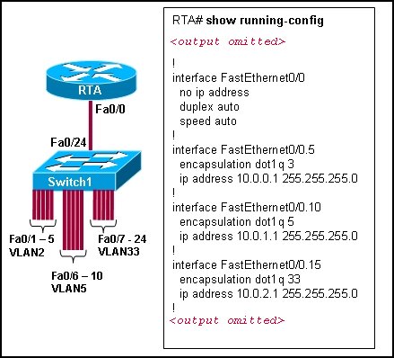
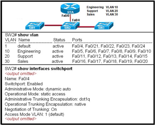
Step1: Find the details of the VLAN assigned to interface fa 0/4 by using the show vlan command on Sw-Ac3.

The above exhibit question has fa 0/4 configured has VLAN1 based on the output from show vlan command.

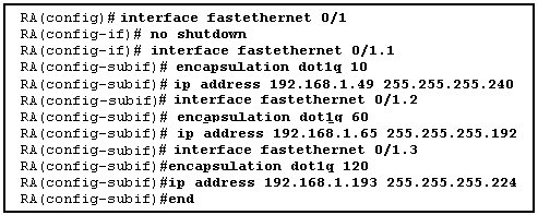
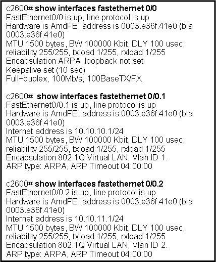
Step2: From the exhibit question we know that VLAN1 is configured on router using sub-interface fa 0/0.1 with IP address 192.168.1.254 /24.

Step3: 192.168.1.254 should be configure as default-gateway address for the host connected to fa 0/4 on switch.

Because VLAN1 corresponds to fa 0/4 on Sw-Ac3 and host connected to fa 0/4 will be member of vlan1.

Question 7:

Out of which ports will frame with source mac-address 0015.5A0Cc.A086 and destination mac-address 000A.8A47.0612 be forwarded ?

Answer:

Step1: Use Show mac-address-table command on the switch.

The output of a show mac-address-table provides the mapping of mac address with port numbers. Search the output for the two mac-addresses provided in the question and select the destination mac address corresponding port number for correct answers.

Step2: If you do not find the above destination mac-address in SHOW MAC-ADDRESS-TABLE output , then the frame will be broadcast or flooded to all ports ( all ports may be ports of particular vlan on switch ,Selection of VLAN will be depending on the source mac-address port vlan membership) except the port it recieved from.

Question 8:

From which switch did Sw-Ac3 receive VLAN information ?

Answer:

Step1: Use Sw-Ac3#show vtp status command .

Sample output of show vtp status command

switch# show vtp status
VTP Version : 2
Configuration Revision : 255
Maximum VLANs supported locally : 1005
Number of existing VLANs : 35
VTP Operating Mode : Server
VTP Domain Name : Lab_Network
VTP Pruning Mode : Enabled
VTP V2 Mode : Enabled
VTP Traps Generation : Disabled
MD5 digest : 0x08 0x7E 0x54 0xE2 0x5A 0x79 0xA9 0x2D
Configuration last modified by 127.0.0.12 at 8-7-02 11:21:43
Local updater ID is 127.0.0.12 on interface EO0/0 (first interface found)

The local updater ID in the above output identifies the ip address of the device which is providing the VLAN information. The address could also be of the switch itself.

Step 2: Show cdp neighbor detail provides the hostname for corresponding to that IP address.

Question 9:

Refer to the exhibit. SwX was taken out of the production network for maintenance. It will be reconnected to the Fa 0/16 port of Sw-Ac3. What happens to the network when it is reconnected and a trunk exists between the two switches?

Answer:

Step1: On switch Sw-Ac3 use show vtp status command. Notice the output for domain name, Both switches must have same domain name configured to exchange vtp messages (exhibit domain name: home-office ).

Step2: If domain name matches, Then note Configuration Revision number of the Sw-Ac3 and compare it with the SwX , Whichever switch has highest configuration revision number will become the vtp updater. The switch which becomes vtp updater will replace other switch vlan information with its own vlan information.

Example if SwX revision number is highest , Then VLAN information that is configured in Sw-Ac3 will be replaced by the VLAN information in the SwX.

CCNA Router Simulator Question - ACL SIM

CCNA EXAM HAVE TWO SIMULATORS.
ACL SIM

CCNA CISA CCNP CISP
Answer:

Select the console on Corp1 router

Configuring ACL

Corp1>enable
Corp1#configure terminal

comment: To permit only Host C (192.168.33.3){source addr} to access finance server address (172.22.242.23) {destination addr} on port number 80 (web)
Corp1(config)#access-list 100 permit tcp host 192.168.33.3 host 172.22.242.23 eq 80

comment: To deny any source to access finance server address (172.22.242.23) {destination addr} on port number 80 (web)
Corp1(config)#access-list 100 deny tcp any host 172.22.242.23 eq 80

comment: To permit ip protocol from any source to access any destination because of the implicit deny any any statement at the end of ACL.
Corp1(config)#access-list 100 permit ip any any

Applying the ACL on the Interface

comment: Check show ip interface brief command to identify the interface type and number by checking the IP address configured.
Corp1(config)#interface fa 0/1
If the ip address configured already is incorrect as well as the subnet mask. this should be corrected in order ACL to work
type this commands at interface mode :
no ip address 192.x.x.x 255.x.x.x (removes incorrect configured ip address and subnet mask)
Configure Correct IP Address and subnet mask :
ip address 172.22.242.30 255.255.255.240 ( range of address specified going to server is given as 172.22.242.17 - 172.22.242.30 )

comment: Place the ACL to check for packets going outside the interface towards the finance web server.
Corp1(config-if)#ip access-group 100 out

Corp1(config-if)#end

Important: To save your running config to startup before exit.
Corp1#copy running-config startup-config


Verifying the Configuration :


Step1: show ip interface brief command identifies the interface on which to apply access list .


Step2: Click on each host A,B,C & D . Host opens a web browser page , Select address box of the web browser and type the ip address of finance web server(172.22.242.23) to test whether it permits /deny access to the finance web Server .


Step 3: Only Host C (192.168.33.3) has access to the server . If the other host can also access then maybe something went wrong in your configuration . check whether you configured correctly and in order.


Step 4: If only Host C (192.168.33.3) can access the Finance Web Server you can click on NEXT button to successfully submit the ACL SIM.

CCNA EIGRP LAB Question

Question:

After adding R3 router, no routing updates are being exchanged between R3 and the new location. All other inter connectivity and Internet access for the existing locations of the company are working properly.
The task is to identify the fault(s) and correct the router configuration to provide full connectivity between the routers.

Access to the router CLI can be gained by clicking on the appropriate host. All passwords on all routers are cisco.

IP addresses are listed in the chart below.


R1

Fa0/0: 192.168.77.33
S1/0: 198.0.18.6
S0/1: 192.160.60.25

R2

Fa0/0: 192.168.60.97
Fa0/1: 192.168.60.113
S0/0: 192.168.36.14

R3

Fa0/0: 192.168.77.34
Fa0/1: 192.168.60.65
Fa1/0: 192.168.60.81

R4

Fa0/0: 192.168.60.129
Fa0/1: 192.168.60.145
S0/1: 192.168.60.26


Answer and explanation:
We should check the configuration of the new added router first because it does not function properly while others work well. From the command line interface of R3 router, enter the show running-config command

From the output above, we know that this router was wrongly configured with an autonomous number (AS) of 22. When the AS numbers among routers are mismatched, no adjacency is formed.
(You should check the AS numbers on other routers for sure)

To solve this problem, we simply re-configure router R3 with the following commands:

R3>enable (you have to enter cisco as its password here)
R3#configure terminal
R3(config)#no router eigrp 22
R3(config)#router eigrp 212
R3(config-router)#network 192.168.60.0
R3(config-router)#network 192.168.77.0
R3(config-router)#no auto-summary
R3(config-router)#end
R3#copy running-config startup-config

Check R1 router with the show running-config command:


Notice that it is missing a definition to the network R3. Therefore we have to add it so that it can recognize R3 router

R1>enable (you have to enter cisco as its password here)
R1#configure terminal
R1(config)#router eigrp 212
R1(config-router)#network 192.168.77.0
R1(config-router)#end
R1#copy running-config startup-config

Now the whole network will work well. You should check again with ping command from router R3 to other routers!

CCNA NAT SIM Question 2


You work as a network technician at networkstepbystep.blogspot.com. Study the exhibit carefully. You are required to perform configurations to enable Internet access. The Router ISP has given you six public IP addresses in the 198.18.32.65 198.18.32.70/29 range.
9tut.com has 62 clients that needs to have simultaneous internet access. These local hosts use private IP addresses in the 192.168.6.65 - 192.168.6.126/26 range.
You need to configure Router1 using the PC1 console.
You have already made basic router configuration. You have also configured the appropriate NAT interfaces; NAT inside and NAT outside respectively.
Now you are required to finish the configuration of Router1.

Solution:
The company has 62 hosts that need to access the internet simultaneously but we just have 6 public IP addresses from 198.18.32.65 to 198.18.32.70/29 => we have to use NAT overload (or PAT)

Double click on the Router 1 router to open it

Router1>enable
Router1#configure terminal
Create a NAT pool of global addresses to be allocated with their netmask (notice that /29 = 248)


Router1(config)#ip nat pool mypool 198.18.32.65 198.18.32.70 netmask 255.255.255.248

Create a standard access control list that permits the addresses that are to be translated

Router1(config)#access-list 1 permit 192.168.6.64 0.0.0.63

Establish dynamic source translation, specifying the access list that was defined in the prior step

Router1(config)#ip nat inside source list 1 pool mypool overload

This command translates all source addresses that pass access list 1, which means a source address from 192.168.6.65 to 192.168.6.126, into an address from the pool named mypool (the pool contains addresses from 198.18.32.65 to 198.18.32.70)

Overload keyword allows to map multiple IP addresses to a single registered IP address (many-to-one) by using different ports

The question said that appropriate interfaces have been configured for NAT inside and NAT outside statements.

This is how to configure the NAT inside and NAT outside, just for your understanding:

Router1(config)#interface fa0/0
Router1(config-if)#ip nat inside

Router1(config-if)#exit

Router1(config)#interface s0/0
Router1(config-if)#ip nat outside


Check your configuration by going to PC2 and type:

C:\>ping 192.0.2.114

The ping should work well and you will be replied from 192.0.2.114

CCNA VTP SIM Question

To configure the router (R2-RC) click on the console host icon that is connected to a router by a serial console cable (shown in the diagram as a dashed black line)


Central Florida Widgets recently installed a new router in their office. Complete the network installation by performing the initial router configurations and configuring RIPV2 routing using the router command line interface (CLI) on the R2-RC.

Name of the router is R2-RC
Enable-secret password is cisco1
The password to access user EXEC mode using the console is cisco2
The password to allow telnet access to the router is cisco3
IPV4 addresses must be configured as follows:
Ethernet network 209.165.202.128/27 - router has last assignable host address in subnet
Serial network is 192.0.2.16/28 - router has last assignable host address in the subnet. Interfaces should be enabled.
Router protocol is RIP V2
Attention :
In practical examinations, please note the following, the actual information will prevail.
1. Name of the router is xxx
2. Enable-secret password is xxx
3. Password to access user EXEC mode using the console is xxx
4. The password to allow telnet access to the router is xxx
5. IP information


Solution:

1) Name the router:

Router>enable
Router#configurate terminal
Router(config)#hostname R2-RC

2) Set secret password:

R2-RC(config)# enable secret cisco1

3) Set password for the console:

R2-RC(config)#line console 0
R2-RC(config-line)#password cisco2
R2-RC(config-line)#login
R2-RC(config-line)#exit

4) Set the Telnet password:

R2-RC(config)#line vty 0 4
R2-RC(config-line)#password cisco3
R2-RC(config-line)#login
R2-RC(config-line)#exit

5) Assign IP address for Ethernet interface (Fa0/0):

The Ethernet network 209.165.202.128/27 has:

Increment:32 (/27 = 255.255.255.224 or 1111 1111.1111 1111.1111 1111.1110 0000)
Network address: 209.165.202.128
Broadcast address: 209.165.202.159 (because 128 + 32 - 1 = 159)

Therefore the last assignable host address in this subnet is 209.165.202.158 and we will assign it to Fa0/0 interface with these commands:

R2-RC(config)# interface fa0/0
R2-RC(config-if)#ip address 209.165.202.158 255.255.255.224
R2-RC(config-if)#no shutdown
R2-RC(config-if)#exit

6) Assign IP address for Serial interface (S0/0/0):

Serial network 192.0.2.16/28 has:

Increment:16 (/28 = 255.255.255.240 or 1111 1111.1111 1111.1111 1111.1111 0000)
Network address: 192.0.2.16
Broadcast address: 192.0.2.31 (because 16 + 16 - 1 = 31)

So the last assignable host address in this subnet is 192.0.2.30. Finally we assign it to s0/0/0 interface:

R2-RC(config)# interface s0/0/0
R2-RC(config-if)#ip address 192.0.2.30 255.255.255.240
R2-RC(config-if)#no shutdown
R2-RC(config-if)#exit

7) Configure RIP v2 routing protocol:

R2-RC(config)#router rip
R2-RC(config-router)#version 2
R2-RC(config-router)#network 209.165.202.128
R2-RC(config-router)#network 192.0.2.16
R2-RC(config-router)#end
R2-RC#copy running-config startup-config

CCNA Drag and Drop SIM Question

Updated from real CCNA exam on 10-20-2008)

This topology contains 3 routers and 1 switch. Complete the topology.

Drag the appropriate device icons to the labeled Device
Drag the appropriate connections to the locations labeled Connections.
Drag the appropriate IP addresses to the locations labeled IP address

(Hint: use the given host addresses and Main router information)
To remove a device or connection, drag it away from the topology.

Use information gathered from the Main router to complete the configuration of any additional routers. No passwords are required to access the Main router. The config terminal command has been disabled for the HQ router. The router does not require any configuration.

Configure each additional router with the following:

Configure the interfaces with the correct IP address and enable the interfaces.
Set the password to allow console access to consolepw
Set the password to allow telnet access to telnetpw
Set the password to allow privilege mode access to privpw

Note: Because routes are not being added to the configurations, you will not be able to ping through the internetwork.
All devices have cable autosensing capabilities disabled.
All hosts are PC’s


explanation:

This is the simplest lab question in four labs you see in the real CCNA exam. First we should identify the types of these routers by using the show cdp neighbors command:

There are 3 columns we should pay more attention to:

+ Local Interface: the interface on the device you are using "show cdp neighbors" command. In this case it is the interface of R-CENTER router

+ Platform: the platform of neighbor device

+ Port ID: the neighbor device's port or interface on which the CDP packets are multicast

From the exhibit, the "Local Interface", "Platform" and "Port ID" columns, we can identify where these four routers should be placed and their corresponding associated ports Finally, use the show running-config command to find out the ip addresses of four interfaces on R-CENTER

And we can easily assign corresponding ip addresses to four neighbor routers, which are on the same network with R-CENTER router's interfaces
Please remember in the real CCNA Exam the routers' types, ip addresses and interfaces may be different! So make sure you understand how it works.

Examenes CCNA 4.0 Exploration Network Fundamentals

Examenes CCNA4.0 Exploration Network Fundamentals
This ebook have questions and answers for CCNA-4.0 Exploration Network Fundamentals
Network step by step happily to provide it to you.

Link download:
http://www.youthgeneration.net/forum/index.php?topic=71.0

Wednesday, November 5, 2008

Use Laptop as Access Point

1. Chose Network and Sharing Center


2. Set up a connection or network


3. setup a wriless ad hoc

4. Next
5. Authenticate
+ Enter network name
+ Security type WEP, WPA2 or none
First chose: No athentication

6. Finished:

7. network bridge
Need network bridge so other computer can access to internet


Monday, November 3, 2008

Testking 640-802 v22

Exam Number/Code: 640-802
Exam Name: Cisco Certified Network Associate

Guarantee your 640-802 success with our 640-802 Exam Resources. Our exams are developed by experiences IT Professionals working in today's prospering companies and date centers. All our practice exams including 640-802 exam guarantee you the exam success you need.

640-802 can be a challenging exam, measuring your 640-802 Exam skills, and compliments the other exams in this certification.

Test King Questions and Answers provide you the complete coverage of the certification exams. Our testing questions and answers was prepared by veteran Certified Experts at Test King. Each preparation exam will make you feel like you're taking the actual exam!

TestKing's commitment to product quality, to our team and to our customers continues to differentiate us from other companies. TestKing uses an experienced team of certified subject-matter experts, technical writers, and technical editors to create and edit the most in-depth and realistic exam questions. Every TestKing product goes through a rigorous, multi-stage editing process to ensure comprehensive coverage of exam objectives.

TestKing products are so comprehensive that IT professionals who use TestKing to prepare for their certification exams feel confident they will pass their exams on the first try--or otherwise be eligible to receive a refund on their purchases. Pass your MCSE, MCSA, MCDBA, Cisco CCNA, CCNP, CCIE, CompTIA A+, HP, IBM, Nortel, Novell, SUN, Oracle , CISSP, CIW, CheckPoint exams on your First Try

Link download is in our forum:
http://www.youthgeneration.net/forum/index.php?topic=68.0

Saturday, October 25, 2008

Pass4Sure 640-802 v3.22

Exam Number/Code: 640-802
Exam Name: Cisco Certified Network Associate

"Cisco Certified Network Associate", also known as 640-802 exam, is a Cisco certification.
Preparing for the 640-802 exam? Searching 640-802 Test Questions, 640-802 Practice Exam, 640-802 Dumps?

With the complete collection of questions and answers, Pass4sure has assembled to take you through 254 Q&As to your 640-802 Exam preparation. In the 640-802 exam resources, you will cover every field and category in CCNA helping to ready you for your successful Cisco Certification

Link Download
Pass: http://networkstepbystep.blogspot.com/

Friday, October 24, 2008

CCNA 4.0 final Question and Answer

CCNA4 version 4.o download -- UPDATED 20081024

1. CCNA4 Module 1
2. CCNA4 Module 2
3. CCNA4 Module 3
4. CCNA4 Module 4
5. CCNA4 Module 5-1
6. CCNA4 Module 5-2
7. CCNA4 Module 5-3
8. CCNA4 Module 6
9. CCNA4 Module 7
9. CCNA4 Module 8

Updated 19/7/2008
CCNA4 Final 100% (update 21/7/2008)

Monday, October 20, 2008

PIX Lab: Tutorial in PIX

Following is PIX LAB tutorial:
  1. Basci PIX Configuration
  2. Installing WebSENSE
  3. Config NAT Stats and Conduits
  4. Config Multiple Interfaces
  5. Config Authentication
  6. Config the Primary PIX Firewall
  7. Verify IPSec Configuration
  8. Passwrod Recovery & Image Update
  9. Configuring the CSIS Feature Set
  10. Configure Cisco Secure ACS NT
  11. Configure AAA and Authentication Proxy
  12. Verify Authentication Proxy Configuration
  13. Configure the PIX as a DHCP Server Configuring PIX as a DHCP Client
  14. Configuring Logging
  15. Configuring Logging -Verification
  16. Denying Outbound Traffic
  17. Allowing Outbound Traffic
  18. Configure PIX to work with Websense
  19. Configure WebSense to Block by URL
  20. WebSense to Block by Workstation
  21. Configure the Fixup Protocol on PIX
  22. Configuring PIX for IDS Signatures
  23. CSACS Install and Add User
  24. Configure IKE and IPsec on the PIX
Link Download:

Let visit this thread in forum to download

Thursday, October 16, 2008

How to build a secure Enterprise Firewall?

Firewalls and their architecture are a critical part of sound network security, but they are only the beginning to a secure enterprise network. In this paper, we will cover the fundamentals of good firewall design using a single multi-homed firewall design with stateful failover. The end result will be a network that is simple to manage, high performance, high availability, high security, and budget saving.

What is the most important aspect?

There has been some fierce debate in design philosophy on whether it is best to have one brand of firewall or more. I personally subscribe to the idea that two are usually not better than one because firewall vulnerabilities are rarely the problem in vast majority of break-ins. Hackers typically don’t need to hack the firewall because they come in through the ports that are already open and exploit the weaknesses on the servers behind the firewall. Additionally, there usually is nothing there for the hacker to hack on the firewall, because any smart administrator will lock that firewall down to drop all connections to the firewall it self except for the designated firewall management stations. Even if for example there is a known vulnerability in Apache or SSH on your firewall, the threat can only come from the designated management stations which are well protected or even turned off

1. Human factors comprises 99% of all firewall compromises
2. The cost of running multiple vendor firewalls may even force you to give up on the very things you need to be most concerned about.
3. Finite resources are usually much better spent hardening a single platform.
4. The biggest problem in firewall security is poor maintenance, bad policy and bad network design

Firewall design goals:

A good firewall policy and network design can mitigate (but not eliminate) the following security risks:

  • The Internet attacking your DMZ servers
  • Any part of your network attacking the Internet
  • Your users or servers attacking your DMZ servers
  • Your DMZ servers attacking your users, servers or even further harming them selves
  • Threats from business partners and extranets
  • Threats from remote offices via WAN connections

The first point is rather obvious; simply by limiting the service port access from the Internet to your DMZ servers, you can greatly reduce the chances that they will be hacked. On an SMTP mail server for example, only TCP port 25 is permitted from the Internet. Therefore, if that SMTP server happened to have a vulnerability in it’s web server service or daemon, it would not be exposed to the Internet where worms and hackers are always on the prowl for port 80 vulnerabilities.

The next point may seem a bit odd, why would one be concerned about protecting the public Internet with one’s own network? While this may seem to be just a good exercise in Netizenship (Internet citizenship), it is also for the selfish purpose of protecting one’s own Internet connection. Take the recent SQL slammer worm for instance; it managed to decimate large segments of the Internet for an entire day. Had there been better firewall policies in place, you could have prevented the DoS (Denial of Service) effect on your Internet connection and also saved the Internet.

One of the least recognized dangers in security is the internal threat. The most expensive firewall on the planet cannot protect your network from “Sneaker net” with conventional designs, a phenomenon where your user walks in to your network with a laptop or disk infected with a virus or worm from home or some other source. A good network design and firewall policy would protect your DMZ servers from your servers and users the same way it protects them from the Internet.

The reverse situation of the above is also a potential threat. Since DMZ servers are exposed to the public Internet, there is a chance that they can be compromised by a hacker or worm. It is essential that you limit the damage that your DMZ servers can do to your internal servers or user stations. Additionally, a tight firewall policy can also prevent DMZ servers from further damaging them selves. If a server is compromised by a hacker through some known or unknown vulnerability, the first thing they will try to do is down load a “root kit”. The firewall policy should prevent the downloading of this deadly payload and make life harder on the attacker.

Additional threats from Extranet partners and Remote office WANs can also be mitigated. Routers that connect these networks using WAN technologies such as frame relay, ISDN, private lease line, or VPN tunnels can be secured by the firewall. Trying to implement security with firewall enabled routers on each and every one of those routers is expensive not only in terms of hardware/software costs, but setup and administration as well. An enterprise firewall can provide simple and centralized management of WAN and Extranet security with additional zones beyond the conventional triple homed design.

The bottom line is that firewalls can limit the flow of traffic between network zones which are broken down by logical organization and functional purposes. A firewall cannot however limit and protect hosts from other hosts within the same subnet because data never passes the firewall for inspection. This is why the more zones a firewall supports, the more useful it is in a well designed enterprise network. This is now easier than ever to accomplish since all of the major players like Cisco and Nokia support trunking of interfaces. A single gigabit port can easily support as many zones as you like and still perform much better than several fast Ethernet ports.

Implementing a good firewall policy:
1. The first critical component of secure firewall architecture is policy design.

In firewall policies, this simply means that unless there is a specific reason that a service needs to be used, that service should be blocked by default.

To implement this default service blocking policy, only one simple firewall rule needs to be implemented globally at the end of all policy sets, the any-any-any-drop rule. This simply means that the default behavior of the firewall will drop all packets from any source to any destination on any service. It is important that this rule is the last rule in any policy set because firewalls act from top to bottom.
==> The narrower these rules are made, the more secure the network is.

For example, users should be permitted outbound ports for common services like HTTP, FTP, media services, but nothing else should be permitted unless there is a special case to allow such traffic. When there is a special case based on a business need, tightly targeted rules should be added when approved. A very common error that administrators make is that they extend user rights to server and DMZ networks. Outbound rules that are appropriate for users are generally not appropriate for servers. When you really think about it, there is no reason that your Web server needs to surf the Web. Servers should serve and are rarely a client. The bottom line is, the DMZ or Server farm should almost always never be permitted to initiate traffic. Servers typically take in requests, but almost never request services from the public Internet except for XML and EDI applications with business partners. Other exceptions can be things like legitimate vendor sites that provide drivers and software updates, but all exceptions should be narrowly defined. Following these strict guidelines can vastly reduce server compromises, to the point that even the intra-subnet spread of worms like Code Red and NIMDA could have been prevented had such policies been in place even if the servers were not patched.

Implementing a good firewall network design:


Figure 1 illustrates a Pix 525 with 2 Gigabit Ethernet ports and 6 100-Mbit Fast Ethernet ports. This is a great way to achieve physical separation of the different subnets needed for an Enterprise network, provided that each port is plugged in to a physically different Ethernet switch. How ever, I can tell you that this is rarely done and is often impractical to deploy more than half a dozen physical switches in the data center for each subnet. More often than not, enterprises employ virtual LANs by segmenting a single physical switch in to multiple bridge groups, which is extremely easy to provision addition ports for any existing subnet or future ones. Because of this and the fact that all the enterprise firewall vendors have added 802.1q trunking support (Cisco came late in February 2003), one can easily use a single Gigabit port to connect the Layer 3 core switch, DMZ, extranet, guest subnet, and any other VLAN subnets that an enterprise needs. Therefore, one can do with out the second Gigabit Ethernet card and 4 port Fast Ethernet card in the PIX 525 shown in figure 1. This has how ever raised need for Layer 2 switch security against things like “VLAN hopping” which is rarely discussed even among experts, but we shall leave that for another piece. But even with the trunked Gigabit port, you should continue using the two built in Fast Ethernet ports for public Internet and stateful failover synchronization. Bottom line, two firewalls in the same class as a PIX 525 can provide enough flexibility and throughput for most enterprise networks.

Figure 2 illustrates the use of the two firewalls in a stateful failover configuration. Network connections were only drawn to the logical firewall to avoid messy connectors in the drawing, but in reality there would be a physical connection to each firewall for each subnet. Those connections could be physically separate cables or a single trunked cable over a single Gigabit connection in to your 802.1q VLAN capable switch. The two built in fast Ethernet ports in a PIX 525 are used for the public Internet connection and the stateful failover synchronizing, and the remaining internal subnets can share the Gigabit port. This configuration is much faster than a configuration with separate fast Ethernet ports that often get congested when trying to do network intensive tasks like tape backup between zones.

The internal side of the firewall can connect the following subnets:

  • Core layer 3 switch
  • DMZ
  • Extranet and WAN
  • Guest zone
  • Others

The core layer 3 connection typically goes to your core switch with routing capability between VLANs. Those VLANs from that core switch may contain hundreds of user VLANs with tens of thousands of users, and server farm VLANs with hundreds of servers that do not get direct Internet exposure. You must understand how ever that there is no firewall between the server farm VLANs and the user VLANs in this example, because user to server traffic is routed by the core L3 switch and never passes through the firewall. There are companies that go to the extreme of putting all of their servers directly behind the firewall and separated from the users, but the management of that many internal servers behind a firewall with a lot of port requirements can be very difficult, so this is not often done.

DMZ is used for servers that need to be accessed from the public Internet. This is directly behind the firewall and is always filtered for traffic.

The Extranet and WAN zone is for the internal interfaces of routers that connect the remote WAN sites and partner sites. Using this configuration allows you to secure against WAN and Extranet sites without having to buy or configure firewall feature sets on the routers them selves. One can even go to the extreme of putting the external interfaces of the routers in a non-NAT zone on the firewall, this helps prevent hackers from compromising the router from the outside. This approach allows the high availability enterprise firewall to secure countless routers.

The guest zone is something new, but this is actually a security feature. Instead of guests connecting to your internal LAN when they need access to VPN or the Internet, have them connect to a guest network with access to the Internet but not your internal LAN. This new zone is extremely useful in the wireless environment. With new Wi-Fi infrastructure technology supporting VLANs and 802.1q trunking, a single wireless Wi-Fi infrastructure can support multiple VLANs, one internal VLAN running it’s own SSID and 802.1x/EAP security, and a guest VLAN that runs a simple WEP password for Internet only access.

VLAN SECURITY

by Rik Farrow

VLAN INSECURITY
VLANS WERE CREATED TO ISOLATE LANS, BUT NOT FOR THE PURPOSES OF SECURITY

Virtual LANs (VLANs) make it possible to isolate traffic that shares the same switch, and even groups of switches. The switch designers had something other than security in mind when they added this form of isolation. VLANs make it possible to share a switch among many LANs, by filtering and limiting broadcast traffic. But this form of isolation relies on software and configuration, not the physical isolation that security people like myself really like to see.

In the last couple of years, some firewalls have become VLAN aware, so that policies can be created that rely on the tags that identify a packet as belonging to a particular VLAN. While firewalls that are VLAN aware add a lot of flexibility useful to Web hosting sites, the tags that these firewalls rely on were not designed with security in mind. VLAN tags can be created by devices other than switches, and valid tags that will fool the firewall can easily be added to packets.

Let's take a look at VLANs, including how they work, why this has little to do with security, and failures of VLANs to maintain isolation. And, if you decide to use VLANs as part of your security architecture, what you should do to minimize the weaknesses involved.
PARTITIONS

The term "switch" today denotes a device that switches network traffic between interfaces, named ports. But not too long ago, switches were called bridges. Even today, if you read the IEEE standards used in switches, the term inevitably used is bridge. And if you are familiar with the way bridges work, you might want to skip ahead.

You use bridges to connect segments of the same LAN, that is, a local network that does not require routing. The bridge software learns which port that network devices have been connected to by examining the source MAC (Medium Access Control) addresses in the packets that the bridge passes. At first, the bridge
knows nothing, and must distribute all the packets it receives to every port. But over time, the bridge learns how to send packets out the correct interface by building spanning trees, an algorithm developed for choosing the right interface and avoiding loops. By sending packets out on a single port, the bridge reduces overall network traffic. Think of the bridge in highway terms, something that connects different roads, and only passes necessary traffic between these roads.

Although the use of bridges does reduce overall network traffic, making networks more efficient, bridges still need to send broadcast packets to all ports. Just as in any LAN, broadcasts mean just that, a message broadcast to all systems. ARP (Address Resolution Protocol) packets provide an important example of broadcast messages.

As bridge hardware grew more capable, with increasing number of ports and the addition of management software, a new feature appeared. You could partition a bridge, split a single bridge into multiple, virtual bridges. When split this way, broadcasts, instead of going to all ports, get limited to only those ports associated with the virtual bridge, and its virtual LAN.

Limiting broadcasts to a VLAN does not seem by itself to prevent a system on one VLAN from hopping to another VLAN-- that is, contacting a system on the same bridge, but a different VLAN. But remember that broadcasts get used to acquire the MAC address that is associated with a particular IP address, using ARP, and without the MAC address, one system cannot communicate with another on the same network. Routers, or switches that support layer three, support passing traffic between VLANs.

Over time, people have begun to consider switches as security devices rather than networking devices. Switches do make sniffing traffic destined for other systems more difficult (but not impossible, as exploits exist for doing so). And switches do produce a software-based isolation between VLANs. But that isolation is imperfect at best.

In a document found on the Cisco web site (See Resources), two scenarios are described where packets can hop VLANs, that is, pass between two VLANs on the same switch. In the first example, systems have established TCP/IP communications on the same VLAN, then the switch gets configured so that one system's port now belongs to a different VLAN. Communications continues between the two systems because each has the MAC address of the other in its ARP cache, and the bridge knows which destination MAC address gets directed to which port. In the second example, someone wishing to hop VLANs manually enters a static ARP entry for the desired system. Doing so requires that the person somehow learns the MAC address of the target system, perhaps through physical access to the target system.

Each of these two examples can be blocked by using switch software that removes the information necessary for passing packets between VLANs. In higher end Cisco switches, separate spanning trees, the tables that map MAC addresses to ports, exist for each VLAN. Other switches either have similar features, or can use configuration to filter the bridging information available to members of each VLAN.

Given the relative dearth of information about hopping VLANs within a single switch, this issue does not appear to be a serious problem.
TRUNKING

Multiple switches can share the same VLANs through configuration and tagging of the packets exchanged between switches. You can configure a switch so that a port acts as a trunk, an interface that can carry packets for any VLAN. When packets get sent between switches, each packet gets tagged, based on the IEEE standard for passing VLAN packets between bridges, 802.1Q. The receiving switch removes the tag and forwards the packet to the correct port or VLAN in the case of a broadcast packet.

802.1Q tags get added to Ethernet headers right after the source address and are four bytes long. The first two bytes contain 81 00, the 802.1Q Tag Protocol Type. The last two bytes contain a possible priority, a flag, and 12 bits for the VLAN Identifier (VID). VIDs can range from 0 to 4095, but both zero and 4095 are reserved values. The default value for the VID is one, and thus also the default value for unassigned ports in a switch configured with VLANs.

An administrator may configure a port to act as a trunk, although the default configuration for Cisco switches is that trunking is "desirable", and a port can negotiate trunking if it discovers that another switch is connected to that port. And, unless the administrator changes the configuration, a trunk port belongs to VLAN 1, which is called its native VLAN. Ports used for trunking can be assigned to any VLAN, and it turns out that putting trunk ports into a VLAN of their own is a good idea.

In 1999, David Taylor posted information to Bugtraq about tests he had run using Cisco switches, in attempts to force packets to hop VLANs. Taylor first attempted to use VLAN tagging to hop VLANs within a single switch, without success. The VLAN tags really have no purpose except for carrying VLAN information between switches, and get ignored if presented on non-trunk ports.

But when Taylor used two switches, he could force packets to hop VLANs under certain conditions. Just as in the early example from Cisco documentation, the MAC addresses of the target system had to be known in advance. The other key condition was that the initiating system, the "attacker", must belong to the same VLAN as the trunk used to connect the switches. In Taylor's first attempt, the attacker and the trunk were both in VLAN one, and the target in VLAN two.

Subsequent investigation by a Cisco employee (you can find this at http://online.securityfocus.com/archive/1/27062) pointed out that this behaviour was not only supported by the 802.1Q standard, but also worked on other, non-Cisco, switches as well.

You can easily prevent VLAN hopping by configuring trunk ports so that their native VLANs do not match the VID of any other VLANs that you have configured. Remember that by default, the native VLAN for a trunk will be VID one, the default for any VLAN. You can choose to set the native VLAN for trunks to be 1001, or any value that your switch supports and is not used for any other VLAN.
FIREWALLS AND VLANS

Now that I have discussed how switches share VLAN information, we can examine firewalls that support VLAN-related policy. Firewalls get packets from VLAN-supporting switches complete with 802.1Q tags in their headers. Although I have only mentioned Ethernet in examples, 802.1Q tagging also applies to other network media, such as ATM and FDDI. What the VLAN-aware firewall can do is extract the tags and use the information within the tags to make policy-based security decisions.

802.1Q tags do not provide authentication. Tags just provide a form of identification, added by switches, that a particular packet came from a particular VLAN. That a firewall would act on this information is no more ridiculous than acting on the source address of a packet, as IP source addresses are also an unauthenticated means of identification--and one that can be spoofed.

Spoofing IP source addresses has been done for many years, and spoofing VLAN tags can be done as well. The most recent Linux operating systems (kernels in the 2.4 vintage) include support for acting as VLAN switches, and can generate any VLAN tag that the local system administrator chooses. Other software exists for spoofing VLAN tags. Taylor used the Network Associates' Sniffer Pro v.2.0.01 to generate packets, and this can be done in software as well.

The key to safely using 802.1Q tags for policy decisions is to design a network where switch trunks get connected to the firewall interface where decisions will be made based on VLAN tags. If there are other routes to this firewall interface, the possibility that packets with spoofed VLAN tags increases. The switches themselves must be properly configured, with trunk ports specifically configured for trunking, and added to a non-default VID.

Implicit in any discussion of switches is protecting administrative access to the switches themselves. Switches and other network equipment typically expose three different means for administrative access: telnet, HTTP, and SNMP. You should always disable methods of administrative access that you don't use, as well as adding access control to the methods that you do use. While the firewall can control access to switches when the source of an attempt is external, the firewall can do nothing about an internal attacker--or one that has gained access to an internal system.

Switches were not designed as security devices. Their use as such simply evolved over time, and is ancillary to their main use as devices that improve network performance. If you use a switch for security reasons, you are relying on the correct configuration of the switch, including understanding not only the standards that the switch software is based upon, but also the correct implementation of those standards. The 802.1Q spec itself is 211 pages long, and is only one of a handful of standards that a compliant switch manufacturer must support.

Any time that you need to segregate networks for serious security purposes, I recommend that you not use a switch.

CCNA VLan Basic knowledge

Some basic knowledge of LANs, different topologies, and working of Local Area Networks is required to proceed further.

What is a VLAN?

To refresh your memory, a Local Area Network (LAN) is a set of connected devices like computers, hubs, and switches sharing the same pool of logical address space. Normally, a router is required to route packets from one LAN to another LAN. Traditionally, all packets within a LAN are broadcast to all other devices connected to that particular LAN.

As a result, a traditional LAN has several disadvantages as below:

* Usable bandwidth is shared among all the devices connected to the LAN
* ALL devices connected within a LAN can hear ALL the packets irrespective of whether the packet is meant for that device or not. It is possible for some unscrupulous node listening to data packets not meant for that.
* Suppose, your organization has different departments. Using a traditional LAN, when any changes take place within the organization, physical cables and devices need to be moved to reorganize the LAN infrastructure.
* A LAN cannot extend beyond its physical boundary across a WAN as in VLANs.

If you are looking for a simple networked solution for a small office, it may be a good idea to have a traditional LAN setup with a few hubs or switches. However, if you are planning for a large building or campus wide LAN for several individual departments, a VLAN is almost essential.

Virtual LANs (VLANs) can be considered as an intelligent LAN consisting of different physical LAN segments enabling them to communicate with each other as if they were all on the same physical LAN segment.

Benefits of VLAN: Several of the disadvantages of traditional LANs can be eliminated with the implementation of VLANs.

1. Improved Performance: In a traditional LAN, all the hosts within the LAN receive broadcasts, and contend for available bandwidth. As a result, the bandwidth is shared among all the connected devices within the LAN segment. If you are running high-bandwidth consumption applications such as groupware or server forms, a threshold point may easily be reached. After a threshold, the users may find the LAN too slow or un-responsive. With the use of VLAN, you can divide the big LAN into several smaller VLANs. For example, if there are two file servers, each operating at 100Mbps, in a traditional LAN both the servers have to share the LAN bandwidth of 100Mbps. If you put both the servers in separate VLANs, then both have an available bandwidth of 100Mbps each. Here the available bandwidth has been doubled.

2. Functional separation of an institute or a company: It is often required to separate the functional groups within a company or institute. For example, it might be necessary to separate HR department LAN from that of Production LAN. Traditionally, it requires a router to separate two physical LANs. However, you can set up two VLANs, one for Finance, and the other for Production without a router. A switch can route frames from one VLAN to another VLAN. With VLAN's it is easier to place a workgroup together eventhough they are physically in different buildings. In this case Finance VLAN does not forward packets to Production VLAN, providing additional security.

3. Ease of Network Maintenance:

Network maintenance include addition, removal, and changing the network users. With traditional LANs, when ever a User moves, it may be necessary to re-configure the user work station, router, and the servers. Some times, it may also be necessary to lay the cable, or reconfigure hubs and switches. If you are using VLANs, many of these reconfiguration tasks become unnecessary. For example, you can avoid network address configuration on the work station and the corresponding router if you use VLAN. This is because, routing traffic within VLANs doesn't require a router.

However, VLAN's add some administrative complexity, since the administration needs to manage virtual workgroups using VLANs.

4. Reduced Cost

VLANs minimize the network administration by way of reduced maintenance on account of workstation addition/deletion/changes. This in turn reduce the costs associated with LAN maintenance.

5. Security

Using a LAN, all work stations within the LAN get the frames meant for all other work stations within the broadcast domain. Since a VLAN splits the broadcast domain into two or more, it is possible to put work stations sharing sensitive data in one VLAN, and other work station in another VLAN. Of course, if two VLANs are not sufficient, you can split the work stations into as many VLANs as required. VLAN's can also be used to set up firewalls, restrict access, and send any intrusion alerts to the administrator.

Wednesday, October 15, 2008

CCNA Video - Router as a DHCP Server

CCNA Video - Router as a DHCP Server

Network Simulation with packet tracer

Network Simulation with packet tracer

Net Sim Tutorial

Net Sim Tutorial

CCNA 3 Ch 1 Lab Intro using Packet Tracer 5.0

Packet Tracer 5.0

Packet Tracer 5.0 is the latest version of Cisco Networking Academy’s comprehensive networking technology teaching and learning software. Innovative features of Packet Tracer 5.0, including powerful simulation, visualization, authoring, assessment, and collaboration capabilities, will help students and teachers collaborate, solve problems, and learn concepts in an engaging and dynamic social environment.

Packet Tracer makes both teaching and learning easier - instructors and students can create their own virtual “network worlds” for exploration, experimentation, and explanation of networking concepts and technologies.

* Instructors can demonstrate technologies and configurations using Packet Tracer to teach complex CCNA-level networking concepts, making it extremely useful for lectures, group and individual labs, assessments, troubleshooting and modeling tasks, homework, games, and competitions.
* Students can design, configure and troubleshoot networks using Packet Tracer’s versatile simulation and visualization environment, which also provides the opportunity and flexibility for additional practice outside of the classroom environment.


Packet Tracer supplements classroom equipment and provides students complementary learning opportunities that are not physically possible to create in the classroom or lab. In addition, Packet Tracer supplements the CCNA curricula and Packet Tracer activities are integrated throughout both CCNA Discovery and CCNA Exploration to provide rich networking technology learning experiences.

Packet Tracer 5.0 offers a unique combination of realistic simulation and visualization experiences, complex assessment and activity authoring capabilities, and opportunities for multiuser collaboration and competition, and is available free of charge to all Networking Academy instructors, students, and alumni. Visit the Packet Tracer 5.0 resource page on Academy Connection today to download this free software and explore the new possibilities in networking education.

Packet Tracer Video Tutorial 5

Packet Tracer Video Tutorial 5

Packet Tracer Video Tutorial 4

Packet Tracer Video Tutorial 4

Packet Tracer Video Tutorial 3

Packet Tracer Video Tutorial 3

Packet Tracer Video Tutorial 2

Packet Tracer Video Tutorial 2

Packet Tracer Video Tutorial 1

Packet Tracer Video Tutorial 1

Saturday, October 11, 2008

ESwitching Chapter 6 - CCNA Exploration: LAN Switching and Wireless (Version 4.0) - Question and Answer

ESwitching Chapter 6 - CCNA Exploration: LAN Switching and Wireless (Version 4.0)
With answer

1


Refer to the exhibit. Switch1 is correctly configured for the VLANs that are displayed in the graphic. The configuration that is shown was applied to RTA to allow for interVLAN connectivity between hosts attached to Switch1. After testing the network, the administrator logged the following report:
Hosts within each VLAN can communicate with each other.
Hosts in VLAN5 and VLAN33 are able to communicate with each other.
Hosts connected to Fa0/1 through Fa0/5 do not have connectivity to host in other VLANs.
Why are hosts connected to Fa0/1 through Fa0/5 unable to communicate with hosts in different VLANs?

The router interface is shut down.

The VLAN IDs do not match the subinterface numbers.

All of the subinterface addresses on the router are in the same subnet.

The router was not configured to forward traffic for VLAN2.

The physical interface, FastEthernet0/0, was not configured with an IP address.

2


Refer to the exhibit. R1 is routing between networks 192.168.10.0/28 and 192.168.30.0/28. PC1 can ping R1 interface F0/1, but cannot ping PC3. What is causing this failure?

PC1 and PC3 are not in the same VLAN.

The PC3 network address configuration is incorrect.

The S1 interface F0/11 should be assigned to VLAN30.

The F0/0 and F0/1 interfaces on R1 must be configured as trunks.

3


Refer to the exhibit. Port Fa0/0 on router R1 is connected to port Fa0/1 on switch S1. After the commands shown are entered on both devices, the network administrator determines that the devices on VLAN 2 are unable to ping the devices on VLAN 1. What is the likely problem?

R1 is configured for router-on-a-stick, but S1 is not configured for trunking.

R1 does not have the VLANs entered in the VLAN database.

Spanning Tree Protocol is blocking port Fa0/0 on R1.

The subinterfaces on R1 have not been brought up with the no shutdown command yet.

4


Refer to the exhibit. PC1 has attempted to ping PC2 but has been unsuccessful. What could account for this failure?

PC1 and R1 interface F0/0.1 are on different subnets.

The encapsulation is missing on the R1 interface F0/0.

An IP address has not been assigned to the R1 physical interface.

The encapsulation command on the R1 F0/0.3 interface is incorrect.

5. A router has two FastEthernet interfaces and needs to connect to four VLANs in the local network. How can this be accomplished using the fewest number of physical interfaces without unnecessarily decreasing network performance?

Implement a router-on-a-stick configuration.

Add a second router to handle the inter-VLAN traffic.

Use a hub to connect the four VLANS with a FastEthernet interface on the router.

Interconnect the VLANs via the two additional FastEthernet interfaces.

6


Refer to the exhibit. Which three statements describe the network design shown in the exhibit? (Choose three.)

This design will not scale easily.

The router merges the VLANs into a single broadcast domain.

This design uses more switch and router ports than are necessary.

This design exceeds the maximum number of VLANs that can be attached to a switch.

This design requires the use of the ISL or 802.1q protocol on the links between the switch and the router.

If the physical interfaces between the switch and router are operational, the devices on the different VLANs can communicate through the router.

7. In which situation could individual router physical interfaces be used for InterVLAN routing, instead of a router-on-a-stick configuration?

a network with more than 100 subnetworks

a network with a limited number of VLANs

a network with experienced support personnel

a network using a router with one LAN interface

8. What distinguishes traditional routing from router-on-a-stick?

Traditional routing is only able to use a single switch interface. Router-on-a-stick can use multiple switch interfaces.

Traditional routing requires a routing protocol. Router-on-a-stick only needs to route directly connected networks.

Traditional routing uses one port per logical network. Router-on-a-stick uses subinterfaces to connect multiple logical networks to a single router port.

Traditional routing uses multiple paths to the router and therefore requires STP. Router-on-a-stick does not provide multiple connections and therefore eliminates the need for STP.

9


Refer to the exhibit. The commands for a router to connect to a trunked uplink are shown in the exhibit. A packet is received from IP address 192.168.1.54. The packet destination address is 192.168.1.120. What will the router do with this packet?

The router will forward the packet out interface FastEthernet 0/1.1 tagged for VLAN 10.

The router will forward the packet out interface FastEthernet 0/1.2 tagged for VLAN 60.

The router will forward the packet out interface FastEthernet 0/1.3 tagged for VLAN 120.

The router will not process the packet since the source and destination are on the same subnet.

The router will drop the packet since no network that includes the source address is attached to the router.

10. Which three elements must be used when configuring a router interface for VLAN trunking? (Choose three.)

one subinterface per VLAN

one physical interface for each subinterface

one IP network or subnetwork for each subinterface

one trunked link per VLAN

a management domain for each subinterface

a compatible trunking protocol encapsulation for each subinterface

11. What are the steps which must be completed in order to enable inter-VLAN routing using router-on-a-stick?

Configure the physical interfaces on the router and enable a routing protocol.

Create the VLANs on the router and define the port membership assignments on the switch.

Create the VLANs on the switch to include port membership assignment and enable a routing protocol on the router.

Create the VLANs on the switch to include port membership assignment and configure subinterfaces on the router matching the VLANs.

12. What two statements are true regarding the use of subinterfaces for inter-VLAN routing? (Choose two.)

subinterfaces have no contention for bandwidth

more switch ports required than in traditional inter-VLAN routing

fewer router ports required than in traditional inter-VLAN routing

simpler Layer 3 troubleshooting than with traditional inter-VLAN routing

less complex physical connection than in traditional inter-VLAN routing

13


Refer to the exhibit. All devices are configured as shown in the exhibit. PC2 can successfully ping the F0/0 interface on R1. PC2 cannot ping PC1. What might be the reason for this failure?

R1 interface F0/1 has not been configured for subinterface operation.

S1 interface F0/6 needs to be configured for operation in VLAN10.

S1 interface F0/8 is in the wrong VLAN.

S1 port F0/6 is not in VLAN10.

14. What is important to consider while configuring the subinterfaces of a router when implementing inter-VLAN routing?

The physical interface must have an IP address configured.

The subinterface numbers must match the VLAN ID number.

The no shutdown command must be given on each subinterface.

The IP address of each subinterface must be the default gateway address for each VLAN subnet

15.


Refer to the exhibit. The network administrator correctly configures RTA to perform inter-VLAN routing. The administrator connects RTA to port 0/4 on SW2, but inter-VLAN routing does not work. What could be the possible cause of the problem with the SW2 configuration?

Port 0/4 is not active.

Port 0/4 is not a member of VLAN1.

Port 0/4 is configured in access mode.

Port 0/4 is using the wrong trunking protocol.

16


Refer to the exhibit. What two conclusions can be drawn from the output that is shown? (Choose two.)

The no shutdown command has not been issued on the FastEthernet 0/0 interface.

Both of the directly connected routes that are shown will share the same physical interface of the router.

A routing protocol must be configured on the network in order for the inter-VLAN routing to be successful.

Inter-VLAN routing between hosts on the 172.17.10.0/24 and 172.17.30.0/24 networks is successful on this network.

Hosts in this network must be configured with the IP address that is assigned to the router physical interface as their default gateway.

17. Devices on the network are connected to a 24-port Layer 2 switch that is configured with VLANs. Switch ports 0/2 to 0/4 are assigned to VLAN 10. Ports 0/5 to 0/8 are assigned to VLAN 20, and ports 0/9 to 0/12 are assigned to VLAN 30. All other ports are assigned to the default VLAN. Which solution allows all VLANs to communicate between each other while minimizing the number of ports necessary to connect the VLANs?

Configure ports 0/13 to 0/16 with the appropriate IP addresses to perform routing between VLANs.

Add a router to the topology and configure one FastEthernet interface on the router with multiple subinterfaces for VLANs 1, 10, 20, and 30.

Obtain a router with multiple LAN interfaces and configure each interface for a separate subnet, thereby allowing communication between VLANs.

Obtain a Layer 3 switch and configure a trunk link between the switch and router, and configure the router physical interface with an IP address on the native VLAN.

18. Which statement is true about ARP when inter-VLAN routing is being used on the network?

When router-on-a-stick inter-VLAN routing is in use, each subinterface has a separate MAC address to send in response to ARP requests.

When VLANs are in use, the switch responds to ARP requests with the MAC address of the port to which the PC is connected.

When router-on-a-stick inter-VLAN routing is in use, the router returns the MAC address of the physical interface in response to ARP requests.

When traditional inter-VLAN routing is in use, devices on all VLANs use the same physical router interface as their source of proxy ARP responses.

19


Refer to the exhibit. Which two statements are true about the operation of the subinterfaces? (Choose two.)

Incoming traffic that has a VLAN ID of 2 is processed by subinterface fa0/0.2.

Incoming traffic with VLAN ID 0 is processed by interface fa0/0.

Subinterfaces use unique MAC addresses by adding the 802.1Q VLAN ID to the hardware address.

Traffic inbound on this router is processed by different subinterfaces, depending on the VLAN from which the traffic originated.

Reliability of both subinterfaces is poor because ARP is timing out.

Both subinterfaces remain up with line protocol up, even if fa0/0 line protocol is down.

20. Which two statements are true about the interface fa0/0.10 command? (Choose two.)

The command applies VLAN 10 to router interface fa0/0.

The command is used in the configuration of router-on-a-stick inter-VLAN routing.

The command configures a subinterface.

The command configures interface fa0/0 as a trunk link.

Because the IP address is applied to the physical interface, the command does not include an IP address

Thursday, October 9, 2008

Troubleshooting Ipconfig

Troubleshooting Ipconfig

An error occurred while renewing interface
Can ping ip but not name
Can ping IP but not hostname after installed/upgraded software
Can receive IP packets but not send them
Can't obtain/renew IP addresses from the DHCP server
Can't ping my own IP address
Cannot use the 2nd NIC
IP address conflicts
No IP while the network cable is disconnected
No operation can be performed on the adapter
One-way ping only
Some Win9x obtain different subnet mask
The DHCP client has obtained an IP address that is already in use on the network
Unexpected network failure or insufficient access or access is denied
Why the ipconfig shows 0.0.0.0 ip even you have assigned a static ip
Why do I get 169.254.x.x IP?

An error occurred while renewing interface

Symptoms: When trying to release and renew the IP address using the Ipconfig command, you may receive the following error message: “An error occurred while renewing interface 'Internet': An operation was attempted on something that is not a socket.”

Cause: These issues may occur if the Winsock registry keys are damaged or corrupted.

Can ping ip but not name

I have a situation here where I could ping an IP of a computer but how come I couldn't ping with its computer name?

1. Incorrect WINS and DNS settings.
2. Incorrect TCP/IP settings
3. Check lmhosts and hosts files

Can ping IP but not hostname after installed/upgraded software

Cause: the may modify the networking configuration in registry.

Can receive IP packets but not send them

Symptoms: When using ipconfig command, you may have no IP address or no Automatic Private IP Addressing (APIPA) address. You may be receiving IP packets but not sending them.

Cause: These issues may occur if the Winsock registry keys are damaged or corrupted.

Can't ping my own IP address

Failure to ping a computer's own IP address is most likely caused by a firewall program or improperly configured.
Can't obtain/renew IP addresses from the DHCP server

Symptoms: 1) you have a DHCP client which may not be able to obtain/renew IP addresses from the DHCP server intermittently. 2) after setup a workstation to obtain an IP address from DHCP, the machine can't ping others and ipconfig /all shows Autoconfiguration IP Address. . . : 169.254.x.x.
Resolutions: 1) If this is XP, obtain the latest service pack for Windows XP.
2) Use the Network Diagnostics tool to identify any failed settings. To do this, go to Help and Support>Use Tools to view your computer information and diagnose problems>Network Diagnostics>Scan your system. When the process finishes, check for any items marked "FAILED" in red, expand those categories, and view the additional details about what the testing showed.
3) Assign a static ip on the client and ping the DHCP server. If you can't ping the DHCP server, check the connection and hardware.
4) If you can ping the DHCP after assigning static ip, check the DHCP settings.
5) Make sure no firewall is running on your LAN.
6) Run Repair this connection if it is XP. Or use netsh to reset TCP/IP configuration.
7) If it is win98/w2k, remove and reinstall TCP/IP.
8) Try to upgrade the new NIC driver.
9) Make sure you don't run out of IPs in the DHCP scope.
10) If you use a router as DHCP, you may want to upgrade the firmware.

Cannot use the 2nd NIC

Symptom: You have two computers and each one has two NICs. You are using the first NIC with 192.168.1.0/24 to connect the Internet and it works. You also want to use the 2nd NIC with crossover cable to connect to each other using the same IP range (one is 192.168.1.10 and another is 192.168.1.11). You can't ping each other (192.168.1.10 and 192.168.1.11).

Resolution: The 2nd NICs should use the different IP range.


IP address conflicts
SYMPTOMS: when trying to set the IP address on a NIC, you may receive the following error message: "The IP address XXX.XXX.XXX.XXX you have entered for this network adapter is already assigned to another adapter Name of adapter. Name of adapter is hidden from the network and Dial-up Connections folder because it is not physically in the computer or is a legacy adapter that is not working. If the same address is assigned to both adapters and they become active, only one of them will use this address. This may result in incorrect system configuration. Do you want to enter a different IP address for this adapter in the list of IP addresses in the advanced dialog box? "
RESOLUTION:
1. If you click Yes, you see the TCP/IP properties where you can change the IP address. Then assign the different IP.
2. If you click No, the IP address is assigned to the network adapter. To resolve this problem, uninstall the ghosted network adapter from the registry: At command prompt, type set devmgr_show_nonpresent_devices=1, and then press ENTER. Type Start DEVMGMT.MSC, and then press ENTER. Click View, and then click Show Hidden Devices. Expand the Network Adapters tree and right-click the dimmed network adapter, and then click Uninstall.

No IP while the network cable is disconnected

Symptoms: your computer has a static IP. However, the ipconfig shows no IP (Media State - Cable Disconnected) while the network cable is disconnected.

Cause: this is by design. If you have some software using TCP/IP whiteout connecting to a network, you may setup it manually.

No operation can be performed on the adapter

Symptoms: when attempting to use ipconfig /release or renew command, you get "No operation can be performed on the adapter as this connection has its media/cable disconnected.

Causes: 1. The network is up-plugged or no NIC. 2. You are using static IP.

One-way ping only

If you can ping other computers and other computers can't ping your computer, this is often caused by an improperly configured firewall
on you computer. For example, ICF should not be enabled on LAN NIC.

Some Win9x obtain different subnet mask

Symptoms: In your domain network, some computers (most are win9x) obtain mask 255.255.255.0 instead of 255.0.0.0 randomly and they can't logon to the Domain. IPCONFIG /renew doesn't fix the problem. If you assign static ip and correct mask, the computer will be able to logon without any problem. If you check the WINS, you may find many bad records.

Possible reasons: you may have another network device (possible a router) except main DHCP functions as a DHCP.

The DHCP client has obtained an IP address that is already in use on the network

Symptom: When trying to renew IP, you may get this error "An error occurred while renewing the interface Local Area Connection: The
DHCP client has obtained an IP address that is already in use on the network. The local interface will be disabled until the DHCP client can obtain a new address."

Resolution: 1. Release and the renew it.
2. Clean the internal DNS and WINS records.
Refer to case 083104LR

Unexpected network failure or insufficient access or access is denied

Symptoms: when trying to use ipconfig /release or renew, you may receive the following message "The following error occurred when releasing adapter Local Area Connection: Unexpected network failure or insufficient access or access is denied"

Cause: You don't have permission to release or renew the IP.

Why do I get 169.254.x.x IP?

Symptom: The Internet Assigned Numbers Authority (IANA) has reserved 169.254.0.0-169.254.255.255 for Automatic Private IP Addressing. If the computer can't get ip from DHCP, APIPA provides an address that is guaranteed not to conflict with routable addresses.

Resolutions: 1) Make sure you have good connection.
2) Check the hardware and settings.
3) Make sure the DHCP is working.
4) For the test, you can assign static ip. If static ip works, it is possible DHCP issue. If static ip doesn't work, check the hardware or connection.
5) WinSock2 stack may be corrupted and need to repair.

Why the ipconfig shows 0.0.0.0 ip even you have assigned a static ip

Question: I have assigned a static ip, subnet to the computer, but the ipconfig shows IP address is 0.0.0.0 and subnet mask 0.0.0.0.. Why?

Answer: An existing IP address on the network has the same IP address. You may use tracert ip, WINS and DNS records to find out another computer using the same IP.

If your laptop users frequently disconnect from one network segment and reconnect to another network segment, they may not be able to access the second network. Resolution will be run ipconfig /registerdns.
Your Ad Here